Because there were no terminals to make connections I wanted, I decided to build the terminals into the board. The terminals were made by winding tinned wire-wrap wire aroung a 4-40 screw and soldering the wire. The wire-wrapped screw was then inserted into a hole in the board and the track on both sides of the board were soldered to the wire wrapped around the screw. When the screw was removed, and the solder on the tracks was filed flat, a threaded terminal was left.
I also decided to incorporate a modular plug on the board. A piece of bus wire soldered to the board slips around the the phone backbone to hold it in place and prevent movement due to the strain from the modular plug.
Like the other boards, this simple board was made by scoring two parallel lines on the the copper with an Xacto knife for each needed separation, then peeling the copper between the lines off of the circuit board. After the separations were made, the board was sanded, and then, tinned using a water-soluable solder paste. All components except the modular connector were surface mounted.
Click on the photos below for construction details and photos.
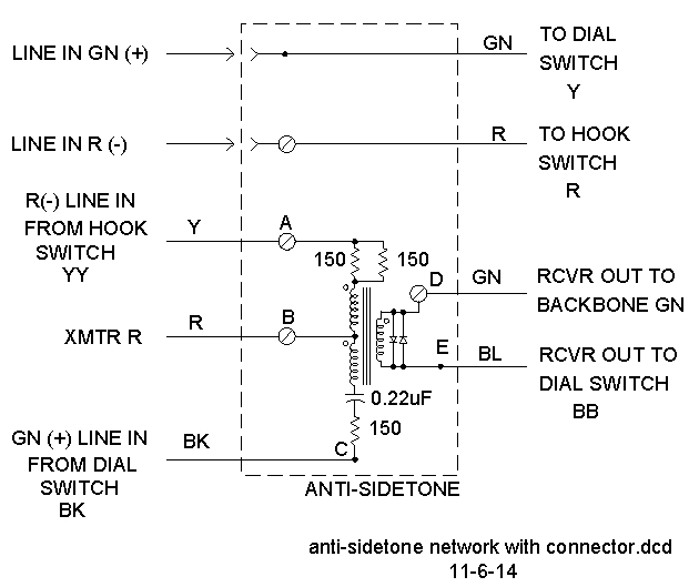 Antisidetone Circuit |
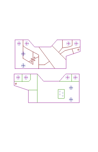 Board Artwork |
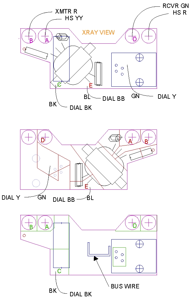 Component Placement |