For this phone, I wanted to make a very small board that I could attach to the backbone in the stem of the phone. The backbone has to be removed for service, and I wanted to have the minimum number of wires coming out of the bottom of the stem tube.
Instead of incorporating a modular plug on the board, I wanted a pigtail modular plug so I would not have an unsightly wire lying around where the phone is displayed. I connect the pigtail to an extention cord whenever I wish to demonstrate the use of the phone.
To fit the board into the stem tube, I had to cut a hole through the board to recess the transformer below the board surface. Other than that, the board is similar the other boards and was made by scoring two parallel lines on the the copper with an Xacto knife for each needed separation, then peeling the copper between the lines off of the circuit board. After the separations were made, the board was sanded, and then, tinned using a water-soluable solder paste. Components were surface mounted.
Click on the photos below for construction details and photos.
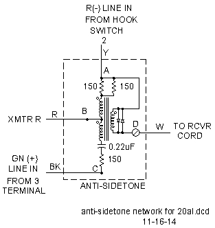 Antisidetone Circuit |
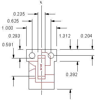 Board Artwork |
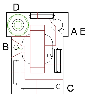 Component Placement |