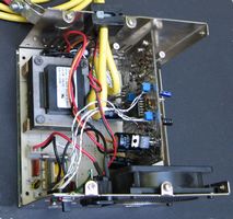
Battery Desulfator
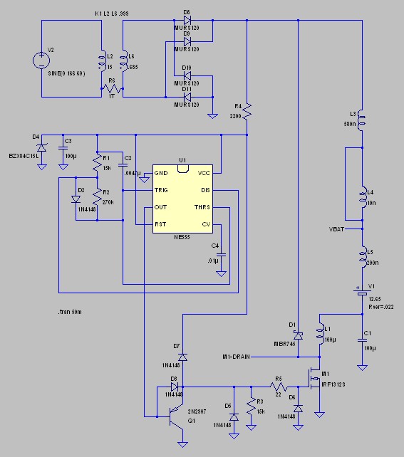
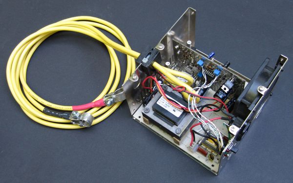
In the middle of building a battery charger from a computer power supply, I discovered numerous articles on battery desulfation and desulfators. I began modeling one of the circuits and playing around with the various ideas put forth in the desulfation forums. This page is a collection of simulations and commentary that lead up to a hardware project.
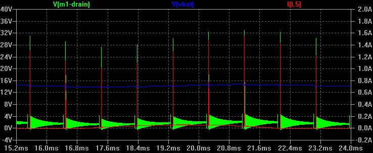
In the plot above the V(vbat) voltage is the battery voltage plus the voltage across the capacitor C1.
Current through the battery, I(L5) = I(V1), is the inductor flyback current plus the current from the diode-bridge charging C1.
Changing the size of capacitor C1 appeared to inversely change the peak charging current. That is, a change from 100uF to 150uF decreased the charging current from 1.8 amps to 1.2 amps; a change from 100uF to 50Uf changed the curent peak from 1.8 to 2.2. This reaction was contrary to the "bigger is better" assumption for C1. I hadn't looked closely at the pulse envelope, or really thought about why this was occuring. It was illogicall to me, and there were a lot of value assumptions in this simulation.
Since I wanted to try a desufonator, and wanted to have it supply a small charging current, and the CIP circuit seemed to do this with one less inductor than the standard desulfator circuit, I decided to model it in more detail (eventually,as I was currently working on building a bathroom, playing with LED flashlights, and working on two old cars).
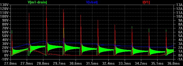
In the initial plot above, I had a transformer primary resistance of 5000 ohms that severely limited the output current capability. When I put in a more realistic 18 ohms, the plot changed radically.
Now the circuit does looked more like the standard desufator circuit with a low-current charger attached. The FET-drain peak voltages seemed very high in the simulation. The capacitor C1 size did not inversely change the peak charging current. It did change the level of non-pulsed charge current from which the current pulses rose.
The problem with the second plot is that it shows only 9 ms detween 27 and 36 ms after starting, it is not a stable circuit yet. When I ran a longer simulation, the 120 hz ripple dropped out of the picture and only the pulses remained. So charging with this circuit seemed to be only the power in the pulse width.
I have attached the text of the simulation after the references. Both the .NET file and the .ASC schematic file for SwitcherCAD are there.You can cut and paste it into a text editor, then save them with the proper extension to run in a simulator.
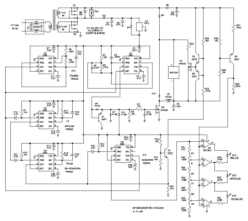
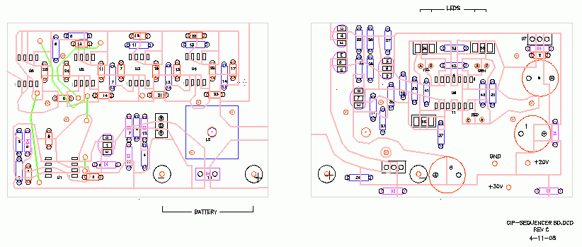
The desulfator shown schematically above is being simulated. So far it shows promise. It combines features from multiple sources and sequences through them using a simple arrangement of 555 timers. Microprocessors are great for things like this, but for many people the programming tools are not available.
The planned cycle has four steps. The first step is to pulse the battery for 15 seconds using a Charged-Induced-Pulse described by desufonator2. The second cycle is a settling period of 1 second. Third is a 100 microsecond pulse that shorts the battery (180 amps?) to remove dendrites. And finally, a 5 second period to measure the battery voltage.
Timer U2 pin 3 is high for 15 seconds and enables the pulsing timer U1. After 15 seconds of pulsing, U2-3 goes low, disabling U1 and triggering U3. U3 times out and triggers U4, which in turn times out and triggers U5. U5 is configured as an asable flip-flop and remains triggered until it is reset by timer U2 pin 3 again going high. the total time for U3, U4, and U5 is limited to 6.5 seconds by the off time of U2.
The high time for U2-3 is calculated as t1 = .693 Rt x C = .693(180k + 100k)47u = 15s. Worked backwards, Rt = t1/(.693C) = 15s/(.693 x 47u) = 280k).
The low time for U2-3 is calculated as t1 = .693 Rt x C = .693(100k)47u = 6.5s. Worked backwards, Rt = t1/(.693C) = 6.5s/(.693 x 47u) = 100k).
The measurement circuit gets a reference voltage from the 555 timer for 5 seconds and compares it with the voltage across the battery. I don't yet know if anything can be obtained from battery measurements at the planned time, as the battery voltage will likely just be the charger surface charge. I will probably leave the measurement components off the circuit board until I can make some actual oscilloscope measurements. I would like to be able to drop the charger offline, or go to a maintenance charge, using the measurement circuit.
Q6 is a level shifter circuit that converts the battery voltage referened to the +voltage supply rail, into an equivalent voltage referenced to ground. The voltage across R28 is equal to: 2 X [ (Vbat/2) - .7 ]
Vbat=2 X [ (V,R28/2) + .7]
| POINT |
% LOW |
% HIGH |
V LOW |
V HIGH |
BAT V LOW |
BAT V HIGH |
| U6-9 |
.49 |
.56 |
5.3 |
6.1 |
6.7 |
7.5 |
| U6-8 |
.77 |
.84 |
8.3 |
9.1 |
9.7 |
10.5 |
| U6-2 |
.9 |
.97 |
9.8 |
10.5 |
11.2 |
11.9 |
| U6-13 |
1 |
1 |
10.84 |
10.84 |
12 |
12 |
| U6-12 |
1 |
1 |
5.3 |
10.5 |
6.7 |
11.9 |
I had three dead batteries for testing. All were murdered by me.
(1) Mustang
The Mustang started this project. It is a Everstart, from Walmart I think, and was fairly new when left to die in an unused Mustang for a year. Then I tried to recharge it and ended up overcharging it. The water in one cell boiled and is low. It reads about 3.42 volts and I think it is a lost cause.
This batterry did not rejuvinate.
(2) Honda
The Honda was a good battery that went dead last winter on a trip to Indiana. It was dead only because someone left the dome lights on all night and the next day. At -20 degrees, on a trip, with no voltmeter, you don't do much troubleshooting, so I just replaced the battery. It reads 12.35 volts but has been setting for a year on the basement floor. If it can be rejuvinated, It could be used in the Mustang.
This battery has been in service for two years, but is only used occasionally as the Mustang is not in daily service.
(3) Suzuki
The Suzuki came out of a Samurai and was used for a backup supply for a while. It has been on the garage floor for two years or so. Condition is unknown.
Condition is now known. It is dead. No rejuvination.
Two more batteries have been attempted, and I am encouraged by the results. Both are from a Fiero. One battery would seem to charge, but discharge rapidly with just a short starter crank. It would not hold a charge and was replaced by a new one. One year later the Fiero was abandoned due to other problems and sat unused for 4 years. Both batterries were recharged using the desulfator. The oldest battery was used to attempt a restart and cranked without weakening until I finally concluded that the injector was clogged and further cranking was a waste of time. To test the newer of the two batteries, I used it to crank the Fiero, and it too showed no signs of weakness.
Dispite numerous attemps to get the voltage monitor circuit to work, it doesn't. I am no longer motivated to tinker with it.
The first two references below have gone dead. These were links to the forum where the CIP desulfonator was proposed. I haven't been able to find any other references to the CIP desulfonator on my internet searches. Maybe this whole idea is bogus. I've started building a prototype, so I'll continue on it. If anyone knows what happened to the llinks, let me know.
http://p198.ezboard.com/Charged-Inductive-Pulse-Hybrid/fleadacidbatterydesulfationfrm13
The EZBoard forum for CIP desulfonators.
http://p198.ezboard.com/MiniCIP-12-volt-5-watt-555-based-PFET-CIP/fleadacidbatterydesulfationfrm13.showMessage?topicID=3.topic
desufator2's modification of a standard AC desufonator to a CIP desulfonator.
http://digilander.libero.it/bjack_italy/desulf/desulf.html
Bjack's desulfator P-Spice model of a lead-acid battery.
desulfator-cip-bjack.net:
* E:\Program Files\SwCADIII\Battery charger\desulfator-cip-bjack.asc
XU1 0 N008 N009 N006 N010 N008 N007 N006 NE555
L1 N012 M1-DRAIN 100µ Rser=162m
D1 M1-DRAIN N003 MBR745
C1 N012 0 100µ Rser=.4 Lser=100n
L3 VBAT N003 580n
L4 VBAT VBAT 10n Rser=100m Rpar=10M Cpar=13p
L5 VBAT N011 200n
V1 N011 N012 12.65 Rser=.022
R1 N006 N007 15k tol=9 pwr=9
R2 N007 N008 270k tol=9 pwr=9
D2 N007 N008 1N4148
C2 N006 N008 .0047µ
C3 N006 0 100µ
R4 N006 N003 2200 tol=9 pwr=9
D4 0 N006 BZX84C15L
C4 0 N010 .01µ
V2 N001 N005 SINE(0 166 60)
M1 M1-DRAIN N014 0 0 IRF1312S
Q1 0 N009 N013 0 2N2907
R3 N013 0 15k tol=9 pwr=9
D3 N009 N013 1N4148
D5 0 N013 1N4148
D6 0 N014 1N4148
R5 N013 N014 22 tol=10 pwr=1
D7 N013 N006 1N4148
D8 N002 N003 MURS120
D9 N004 N003 MURS120
D10 0 N002 MURS120
D11 0 N004 MURS120
L2 N001 N005 15 Ipk=2 Rser=5k
L6 N002 N004 .685 Ipk=10 Rser=.5
R6 N004 N005 1T
.model D D
.lib E:\Program Files\SwCADIII\lib\cmp\standard.dio
.model NPN NPN
.model PNP PNP
.lib E:\Program Files\SwCADIII\lib\cmp\standard.bjt
.model NMOS NMOS
.model PMOS PMOS
.lib E:\Program Files\SwCADIII\lib\cmp\standard.mos
.tran 50m
K1 L2 L6 .999
.lib NE555.sub
.backanno
desufator-cip-bjack.asc: highlight, copy, paste into text file with.asc extention for schematic to run in SWCADII.
Version 4
SHEET 1 1496 1140
WIRE -352 -464 -576 -464
WIRE -80 -464 -272 -464
WIRE -64 -464 -80 -464
WIRE 64 -464 0 -464
WIRE 192 -464 64 -464
WIRE 384 -464 192 -464
WIRE 624 -464 384 -464
WIRE -64 -384 -112 -384
WIRE 64 -384 64 -464
WIRE 64 -384 0 -384
WIRE -576 -352 -576 -464
WIRE -352 -352 -352 -464
WIRE -272 -352 -272 -464
WIRE -80 -256 -80 -464
WIRE -64 -256 -80 -256
WIRE 64 -256 0 -256
WIRE -352 -208 -352 -272
WIRE -272 -208 -272 -272
WIRE -576 -176 -576 -272
WIRE -352 -176 -352 -208
WIRE -352 -176 -576 -176
WIRE -272 -176 -272 -208
WIRE -112 -176 -112 -384
WIRE -112 -176 -272 -176
WIRE -64 -176 -112 -176
WIRE 64 -176 64 -256
WIRE 64 -176 0 -176
WIRE 192 -160 192 -464
WIRE 624 -128 624 -464
WIRE 64 -112 64 -176
WIRE -496 -32 -576 -32
WIRE -368 -32 -496 -32
WIRE -224 -32 -368 -32
WIRE 96 -32 -224 -32
WIRE 192 -32 192 -80
WIRE 192 -32 96 -32
WIRE -576 -16 -576 -32
WIRE -496 -16 -496 -32
WIRE 624 16 624 -48
WIRE 624 16 560 16
WIRE -368 32 -368 -32
WIRE -272 32 -368 32
WIRE -272 48 -272 32
WIRE -576 80 -576 48
WIRE -496 80 -496 48
WIRE -160 112 -192 112
WIRE 96 112 96 -32
WIRE 96 112 64 112
WIRE -448 128 -512 128
WIRE -368 128 -368 112
WIRE -368 128 -448 128
WIRE -192 128 -192 112
WIRE -368 160 -368 128
WIRE 624 160 624 16
WIRE -448 176 -448 128
WIRE -272 176 -272 112
WIRE -160 176 -272 176
WIRE 160 176 64 176
WIRE -160 240 -192 240
WIRE 128 240 64 240
WIRE -448 288 -448 240
WIRE -368 288 -368 240
WIRE -368 288 -448 288
WIRE -272 288 -272 176
WIRE -272 288 -368 288
WIRE 560 288 560 16
WIRE 624 288 624 240
WIRE 624 288 560 288
WIRE -224 304 -224 -32
WIRE -160 304 -224 304
WIRE 96 304 64 304
WIRE 624 320 624 288
WIRE 624 320 560 320
WIRE 96 384 96 304
WIRE 624 384 624 320
WIRE 96 480 96 448
WIRE -272 528 -272 288
WIRE 128 528 128 240
WIRE 128 528 -272 528
WIRE 624 528 624 464
WIRE -512 560 -512 128
WIRE 160 560 160 176
WIRE 160 560 -512 560
WIRE 192 640 192 -32
WIRE 192 640 -48 640
WIRE 624 640 624 592
WIRE 624 640 464 640
WIRE 464 672 464 640
WIRE 384 688 384 -464
WIRE 624 704 624 640
WIRE -48 768 -48 640
WIRE 384 800 384 752
WIRE 384 800 208 800
WIRE 464 800 464 752
WIRE 464 800 384 800
WIRE 464 832 464 800
WIRE 624 832 624 768
WIRE -112 912 -144 912
WIRE -48 912 -48 832
WIRE 144 912 -48 912
WIRE 208 912 144 912
WIRE 272 912 208 912
WIRE 384 912 352 912
WIRE 416 912 384 912
WIRE 208 944 208 912
WIRE 384 960 384 912
WIRE -48 976 -48 912
WIRE 144 992 144 912
WIRE 464 1008 464 928
WIRE -192 1024 -192 240
WIRE -144 1024 -144 912
WIRE -144 1024 -192 1024
WIRE -112 1024 -144 1024
WIRE 208 1056 208 1024
WIRE 384 1056 384 1024
WIRE 144 1088 144 1056
WIRE -48 1120 -48 1072
FLAG 624 832 0
FLAG -192 128 0
FLAG 96 480 0
FLAG -496 80 0
FLAG -576 80 0
FLAG 560 320 VBAT
FLAG 208 800 M1-DRAIN
FLAG 64 -112 0
FLAG 464 1008 0
FLAG 208 1056 0
FLAG -48 1120 0
FLAG 384 1056 0
FLAG 144 1088 0
SYMBOL Misc\\NE555 -48 208 R0
SYMATTR InstName U1
SYMBOL ind 448 656 R0
SYMATTR InstName L1
SYMATTR Value 100µ
SYMATTR SpiceLine Rser=162m
SYMBOL schottky 400 752 R180
WINDOW 0 24 72 Left 0
WINDOW 3 24 0 Left 0
SYMATTR InstName D1
SYMATTR Value MBR745
SYMATTR Description Diode
SYMATTR Type diode
SYMBOL cap 608 704 R0
SYMATTR InstName C1
SYMATTR Value 100µ
SYMATTR SpiceLine Rser=.4 Lser=100n
SYMBOL ind 640 -32 R180
WINDOW 0 36 80 Left 0
WINDOW 3 36 40 Left 0
SYMATTR InstName L3
SYMATTR Value 580n
SYMBOL ind 608 144 R0
SYMATTR InstName L4
SYMATTR Value 10n
SYMATTR SpiceLine Rser=100m Rpar=10M Cpar=13p
SYMBOL ind 608 368 R0
SYMATTR InstName L5
SYMATTR Value 200n
SYMBOL Misc\\cell 624 528 R0
WINDOW 123 0 0 Left 0
WINDOW 39 24 84 Left 0
SYMATTR SpiceLine Rser=.022
SYMATTR InstName V1
SYMATTR Value 12.65
SYMBOL res -384 16 R0
SYMATTR InstName R1
SYMATTR Value 15k
SYMATTR SpiceLine tol=9 pwr=9
SYMBOL res -384 144 R0
SYMATTR InstName R2
SYMATTR Value 270k
SYMATTR SpiceLine tol=9 pwr=9
SYMBOL diode -464 176 R0
SYMATTR InstName D2
SYMATTR Value 1N4148
SYMBOL cap -288 48 R0
SYMATTR InstName C2
SYMATTR Value .0047µ
SYMBOL cap -512 -16 R0
SYMATTR InstName C3
SYMATTR Value 100µ
SYMBOL res 208 -64 R180
WINDOW 0 36 76 Left 0
WINDOW 3 36 40 Left 0
SYMATTR InstName R4
SYMATTR Value 2200
SYMATTR SpiceLine tol=9 pwr=9
SYMBOL zener -560 48 R180
WINDOW 0 24 72 Left 0
WINDOW 3 24 0 Left 0
SYMATTR InstName D4
SYMATTR Value BZX84C15L
SYMBOL cap 112 448 R180
WINDOW 0 24 64 Left 0
WINDOW 3 24 8 Left 0
SYMATTR InstName C4
SYMATTR Value .01µ
SYMBOL voltage -576 -368 R0
WINDOW 123 0 0 Left 0
WINDOW 39 24 132 Left 0
SYMATTR InstName V2
SYMATTR Value SINE(0 166 60)
SYMBOL nmos 416 832 R0
SYMATTR InstName M1
SYMATTR Value IRF1312S
SYMBOL pnp -112 1072 M180
SYMATTR InstName Q1
SYMATTR Value 2N2907
SYMBOL res 192 928 R0
SYMATTR InstName R3
SYMATTR Value 15k
SYMATTR SpiceLine tol=9 pwr=9
SYMBOL diode -112 928 R270
WINDOW 0 32 32 VTop 0
WINDOW 3 0 32 VBottom 0
SYMATTR InstName D3
SYMATTR Value 1N4148
SYMBOL diode 160 1056 R180
WINDOW 0 24 72 Left 0
WINDOW 3 24 0 Left 0
SYMATTR InstName D5
SYMATTR Value 1N4148
SYMBOL diode 400 1024 R180
WINDOW 0 24 72 Left 0
WINDOW 3 24 0 Left 0
SYMATTR InstName D6
SYMATTR Value 1N4148
SYMBOL res 256 928 R270
WINDOW 0 32 56 VTop 0
WINDOW 3 0 56 VBottom 0
SYMATTR InstName R5
SYMATTR Value 22
SYMATTR SpiceLine tol=10 pwr=1
SYMBOL diode -32 832 R180
WINDOW 0 24 72 Left 0
WINDOW 3 24 0 Left 0
SYMATTR InstName D7
SYMATTR Value 1N4148
SYMBOL diode -64 -448 R270
WINDOW 0 32 32 VTop 0
WINDOW 3 0 32 VBottom 0
SYMATTR InstName D8
SYMATTR Value MURS120
SYMBOL diode -64 -368 R270
WINDOW 0 32 32 VTop 0
WINDOW 3 0 32 VBottom 0
SYMATTR InstName D9
SYMATTR Value MURS120
SYMBOL diode 0 -272 R90
WINDOW 0 0 32 VBottom 0
WINDOW 3 32 32 VTop 0
SYMATTR InstName D10
SYMATTR Value MURS120
SYMBOL diode 0 -192 R90
WINDOW 0 0 32 VBottom 0
WINDOW 3 32 32 VTop 0
SYMATTR InstName D11
SYMATTR Value MURS120
SYMBOL ind2 -368 -368 R0
SYMATTR InstName L2
SYMATTR Value 15
SYMATTR Type ind
SYMATTR SpiceLine Ipk=2 Rser=18
SYMBOL ind2 -288 -368 R0
SYMATTR InstName L6
SYMATTR Value .685
SYMATTR Type ind
SYMATTR SpiceLine Ipk=10 Rser=.5
SYMBOL res -256 -224 R90
WINDOW 0 0 56 VBottom 0
WINDOW 3 32 56 VTop 0
SYMATTR InstName R6
SYMATTR Value 1T
TEXT -512 632 Left 0 !.tran 50m
TEXT -376 -488 Left 0 !K1 L2 L6 .999


.end
Copyright Dale Thompson,
28 August 2007 through
last revision on 25 April 2017.
