LED Bicycle Headlight and Taillight
General
I wanted a bike headlight and taillight for my grandson's bicycle. If I used batteries to power the lights, the batteries would be dead when needed, because most bike riding by 9 year olds is done in daylight. The batteries would thus be unused for long periods. My plan to solve this situation was to use a dynamo instead of batteries.
I ordered an LED headlight and taillight with a dynamo for seven bucks. In my day LED meant light-emitting-diode, but evidently in China LED means something else. Maybe filament. So I decided to use the dynamo and convert the filament lights to LEDs.
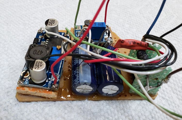
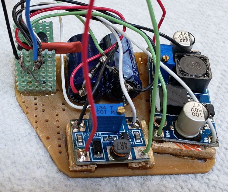
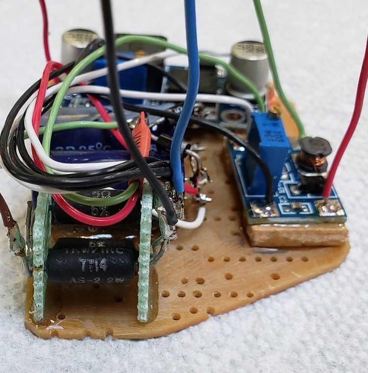
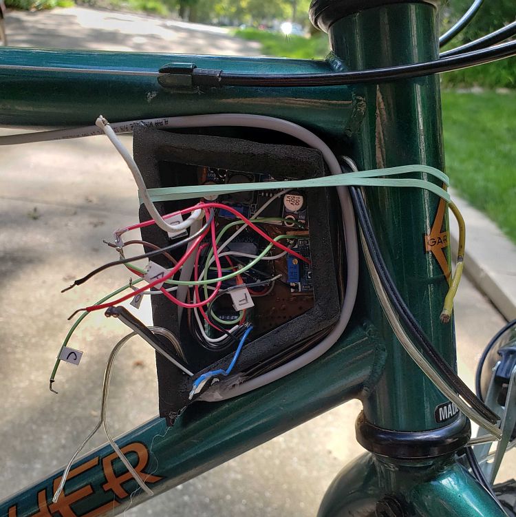
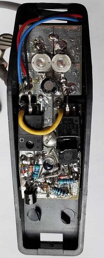
Following is the first working prototype model. It works as desired, but I had to take a number of twists and turns to get there.
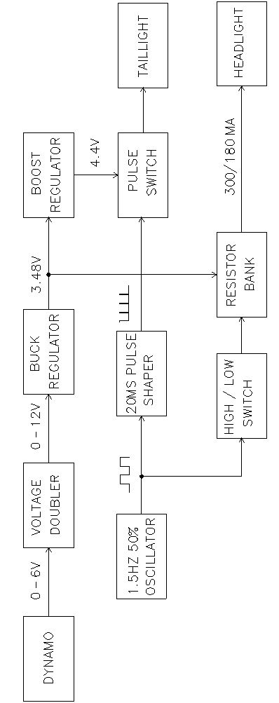
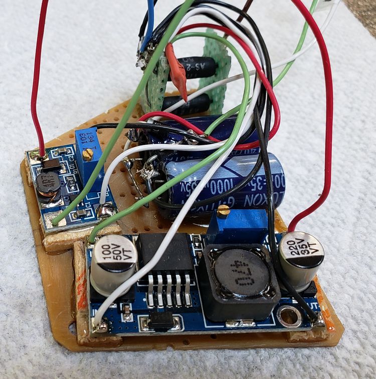
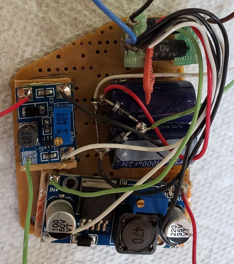
There are four elements in the lighting system: a power box containing a voltage doubler, an up converter, a down converter, and a resistor bank; a taillight containing a pulsing controller circuit; a dynamo; and a headlight.
First, a voltage doubler gets the 6-volt rated dynamo output quickly above 4 volts. It lingers slightly below 4 volts when the bike is just barely moving.
To keep the voltage at 3.48 volts so the headlight current stays at 300mA when bike speed increases, I used a buck regulator . The buck regulator also feeds 3.48 volts to a boost regulator that supplies 4.4 volts to the taillight circuit.
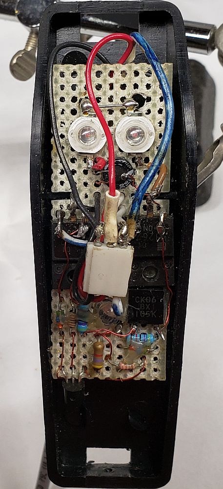
The taillight has two power FETs driven by a self flashing LED. One FET cycles the headlight to high and low output by connecting and disconnecting a resistor bank contained in the power box. The second FET supplies 20 ms, 4.4V pulses to the two power LEDs connected in series.
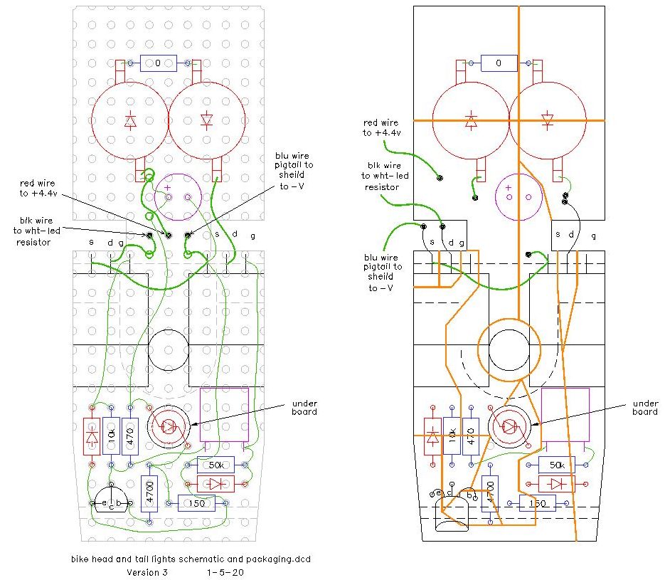
Wiring connections and wire colors are a mess due to using what I had available for a prototype. So as to not further confuse myself, I will keep the same color wires in the two systems I am building for my wife and grandson.
Block Diagram
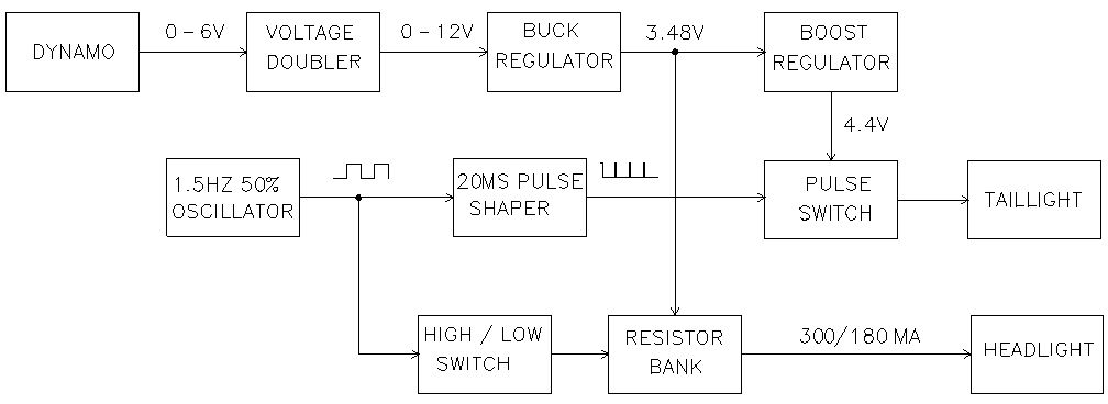
Bike Light System Block Diagram
|
The dynamo is rated 6V at 3W, which is 500mA.
A voltage doubler is used to get the dynamo voltage up to the minimum buck-regulator input voltage of 4 volts at low starting speed.
Buck-regulator output is adjusted for 3.48V. Maximum output current is .92x(3W/3.48V)=793mA
The headlight has two equal period light levals. High is 300mA, low is 180; the average is 240mA. So there is 553mA left for the taillight.
The taillight uses a self-flashing LED with a 50% duty cycle and an average currentof 8 mA.
The two power LEDs draw 180mA at 4.4 V, but with only a 20ms pulse the average current is only 20mA. Total taillight current is only 28mA. The average power is 4.4V times 28mA, or 123.2 mW.
To get 4.4 V a boost regulator was used. Input current needed to produce 123.2 mW output is 123.2 divided by the 3.48V supplied to the boost regulator by the buck regulator. Ideally this would be35.4mA. At 95% efficiency, more current is needed (35.4/95%=37.3).
So finally: total input current is 240mA average headlight current plus 37.3mA taillight current or 277mA average current.
Circuit
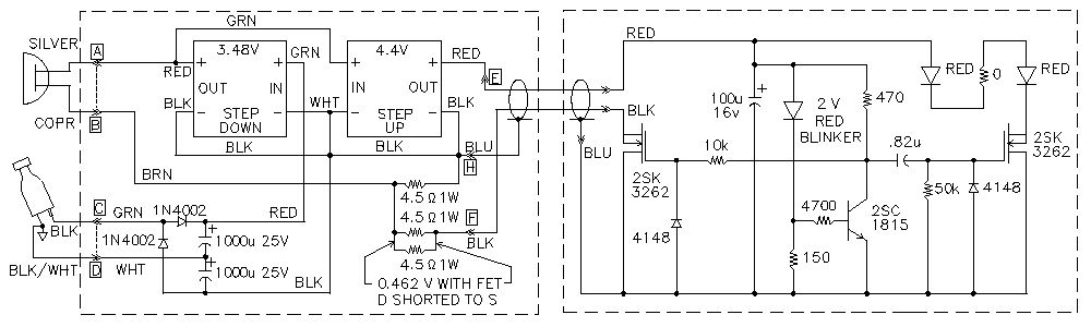
Schematic Diagram
|
Construction
Parts List
| Item | Selection Criteria | Part Number | Specifications | Source | Cost | Comment |
Dynamo
light set |
6V 500mA | Dynamo
light set | 6v 500mA | Ebay | $7.12 | 3pc $21.34 |
Buck
Regulator |
- Low minimum input voltage (2V or less)
- High maximum input voltage (at least 25V)
- Output current (1A or more)
- 10-turn voltage adjustment potentiometer
- High efficiency (at least 90%)
- Board size ( small but able to dissipate heat)
- Price (under $1) |
LM2596DC-DC
Converter |
- +3.2V to 40V input
- +1.23V to 30V output
- 3A output
- LM2596
- 10 turn pot
- 92%efficiency
- 1x1 inch
|
Ebay | $0.52 | 4pc $2.10 |
Boost
Regulator |
- Low minimum input voltage (3V or less)
- Output current (1A or more)
- 10-turn voltage adjustment potentiometer
- High efficiency (at least 90%)
- Board size ( small but able to dissipate heat)
- Price (under $1)
|
SX1308 DC-DC
Boost Converter |
- +2V to 24V input
- +2V to 28V output
- 2A output
- 20 turn pot
- 95%efficiency
- 7/8x5/8 inch
|
Ebay | $0.74 | $3.15 for 4pc | |
| Power FETs |
2.0V VGS (th) | Fuji 2SK3262 | 2.0V VGS (th) @400mA | On Hand | $0.00 | |
4.5 Ohm
Resistors |
4.5ohm +/- 1% 2W | RCL T2B-79 | 4.5ohm +/- 1% 2W | On Hand | $0.00 | |
White LED
Emitter |
- One watt
- Cool white 6000K
- Large metal PCB as no heatsink planned |
Cree XP-E2 |
- One watt (no heatsink)
- Cool white 6000K
- 20mm metal PCB
- +3.2 to 3.6V
- 350 to 1000mA
- 114lm
|
Ebay | $0.70 | 5pc $3.52 |
Red LED
Emitters |
- One watt (no heatsink)
- 2.2V@300mA
|
Red 1W
LED Emitter |
- One watt (no heatsink)
- 2.3V@350mA
- 2.0V@125mA
- 40lm@350mA
- 15lm@125mA |
Ebay | $0.13 | 10pc $1.27 |
1.5Hz Red
Flashing LED |
| 1.5Hz Blink
LED 5MM | | Ebay | $0.08 | 50pc $3.98 |
| Power Box |
-Waterproof
-Removeable
-Metal
-Accessible |
Metal Box |
-Waterproof
-Removeable
-Metal
-Accessible |
On Hand | $0.00 | Constructed |
| Total | | | | | $9.69 | |
Construction Details
Bike Light Voltage Adustment
If a regulator has never been adjusted, the last volage it was adjusted to is unknown, or it cannot be adjusted, turn the potentiometer counter-clockwise 20 turns then start adjusting.
1. Disconnect the headlight, the plug to taillight, and the dynamo wire.
2. Connect a 6VAC transformer to thedynamo wire and bike frame ground; do not connect to regulator grounds.
3. Check voltage at the output of the voltage doubler or step-down regulator input. It should be around 12- to 18-Vdc.
4. Short the BLU wire going to the tail light plug to the BLK wire going to the tail light plug.
5. Adjust the step-down regulator for 3.48 Vdc between the step-down regulator plus and minus terminals.
6. While watching the voltmeter, connect the headlight and make sure the voltage does not exceed 3.48 volts as the headlight LED warms up.
7. Adjust the step-up regulator for 4.4 Vdc between the step-up regulator plus and minus terminals.
8. Disconnect the transformer and allow the voltage-doubler capacitors to discharge gradually.
Other details
The headlight had to be slightly modified. First, the ground connection had to be removed. Second the lense had to be replaced with a piece of clear flat plastic. The original lense had focusing stripes in it to cover a wider area. The result with a LED emitter was to create a non-symmetrical light pattern.
The light bulb was removed and a shortened 3/8x18 hex bolt with a flattened head was screwed into the bulb socket. To flatten the bolt head, the bolt was chucked in a drill press and a file was used on the spinning bolt. The white LED circuit board was JB Weld glued to the flattened bolt head and a two conductor wire was soldered to the circuit board. A two-conductor wire is needed because the white LED is floating about ground.
To permit easy removal of a defective module from the power box, the regulator modules we're glued to thin wood strips after wire pigtails were attached. Then the wood strips
we're glued to a mother board that had been glued to the bottom of the power box.
The odd shaped power box was constructed from available metal to fit the bike. Two side plates clamp the box to the bike. One side plate is glued to the bottom of the box.. The other side plate is screwed into a clamp plate inside the box. A thin rubber seal is compressed by the second plate to keep out water.
Does It Work?
Yes.
The short video clip below shows how well.
Copyright Dale Thompson,
23 June 2020 through
last revision on 5 January 2021