Can a typical 12.6 Vrms, 1 Arms center-tapped transformer be used to make a 5Vdc/0.1A and 12Vdc/0.95A regulated power supply?
No. The best possible is 5Vdc/0.1A and 12Vdc/0.8A
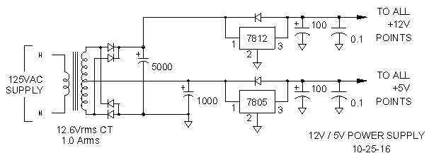 Schematic Diagram of Circuit with Full-Wave-Bridge for 12 Vdc and Center-Tapped-Transformer for 5 Vdc (not final version) |
Voltage
Peak V = Vrms x sqrt2
Peak V12 = 12.6×1.414 = 17.8 Vpk
Peak V5 = 6.3×1.414 = 8.9 Vpk
12V bridge has two diodes in path; subtract 2.0 V.
5V rectifier has only one diode inpath; subtract 1.0 V
Peak V12 = 17.8 - 2.0 = 15.8 Vpk
Peak V5 = 8.9 - 1.0 = 7.9 Vpk
7812 and 7805 have a two-volt dropoutrequirement.
7812 Vin = 12 + 2 = 14
7805 Vin = 5 + 2 = 7 V
Capacitor size = I x dt/dv = I x (time between voltage peaks) / Vpk – Vin
dt = time between voltage peaks = 1 / frequency = 1 / 60 Hz x 2 for full-wave rectifier = 1/120Hz = 8.3ms
C equals I x dt/dv
C12V= 1A x 8.3ms / 15.8 -14 = 8.3 /1.8 = 4.6 mF = 4600uF = 5000 uF
C5V/0.1A = 0.1A x 8.3ms / 7.9 -7 = 0.83 /0.9 = 0.922 mF = 922uF = 1000 uF
(For future reference:)
(C5V/1A = 1A x 8.3ms / 7.9 -7 = 8.3 /0.9 = 9.2 mF = 9,222uF = 10,000 uF)
So voltage is not a problem, but is current a problem?
Current
Transformer current rating equals the 12V current plus one half of the 5V current. Current for the 12V supply passes through the full secondary winding on each half cycle. The 5V supply current passes through one half of the winding on the positive half cycle and through the other one half of the winding onthe negative half cycle. Since the maximum current through the transformer is 1A and one-half of the 5V/0.1A is 0.05A, the 12V supply maximum should be 0.95A
But wait, I have seen the formula Idc = 2 x Imax / 3.14 used for maximum transformer current. Imax = Irms x sqrt2 = Imax x 1.414, so 2 x Imax sqrt2 = 2.828/3.1416 = 0.9. Hammond transformer also says it is 0.90 Irms.
Well, by definition, Prms has the same heating production in a resistor as Pdc. Since P = I2 x R, and R is a fixed value, then Irms must equal Idc. No, this is not a resistor, and I don't want to go into why the temperature of a resistor passing 12A at 50% duty cycle doesn't equal the temperature of a resistor passing 6A at 100% duty cycle. Hammond and the formula are correct. Idc will be 0.90 Irms.
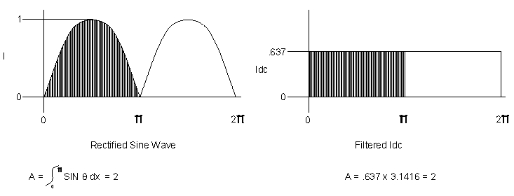 |
A = /0 pi sin
Squeeze this area into a rectangle with width equal to pi and height equal to IDC:
Idc = A / pi = 2 / 3.1416 = .637 Imax
For the 1Arms transformer:
Irms = 1A
Imax = Irms x sqrt2 = 1 x 1.414 = 1.414A
Idc = 0.637 x Imax = 0.637 x 1.414 = 0.9A
With only 0.9A available, this transformer can only produce 5Vdc/0.1A and 12Vdc/0.8A
Facts and fallacies
Transformer Irms required for a full-wave bridge is Idc x pi / 2 x sqrt 2, not 1.6 x Idc.
Idc = 0.9 x Irms of transformer.
Idc = 0.637 Imax of transformer, not 0.707 Imax.
Real World
There is a lot of capacitance following the bridge rectifier in this circuit. That capacitance looks like a short circuit during the fist few ac cycles as the capacitors are charged, and it is possible to blow out the bridge rectifier diodes with the inrush current, which can exceed 50 Amperes. Something has to be done.
An NTC thermistor in the ground lead of the bridge rectifier might work during the initial startup, but if power is interrupted for a short time, and the thermistor doesn't have time to cool down, the diode bridge is in jeopardy. My solution is to add an inrush limiter. Yikes! Eight more components! Isn't this supposed to be a simple power supply? Welcome to the real world.
This is a junk box project, so back to the junk box for an N-channel power FET from a scrapped monitor. A 10-ohm resistor in parallel with the FET slowly lets current into the filter capacitors as the gate capacitor is charged, thus no surge. If input power is ever interrupted, a diode discharges the gate capacitor, and the FET again slowly lets current into the filter capacitors as the gate capacitor is recharged. After the capacitors are charged, the FET is fully turned on to prevent the FET and the resistor from generating heat.
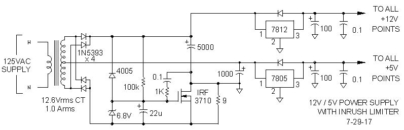 Schematic Diagram of Circuit with Full-Wave-Bridge for 12 Vdc and Center-Tapped-Transformer for 5 Vdc With Inrush Current Limiter |