Dial Frequency and Pulse-Width Tester
General
This project was started a couple of years ago and was modeled using Linear Technology's SwitcherCAD/LTSpice program. When I built it, it didn't work, and after a fair amount of troubleshooting, I quit on it. Then I restored a 1948 Stromberg-Carlson phone and couldn't tweak the dial into working with my Verizon ONT. Out came the shelved project. I got it to work by a lot of Mini-Clipped components and potentiometers in the R-C delay portion of the NAND gate inputs. So now it works, but SwitcherCAD says it dosen't. I have completed the webpage with the schematic showing what I have that works. But the resistor values that work in SwitcherCAD are 55k for the 11600 (5600+6000) resistor and 73k for the 24k (18k+6k) resistor.
Since finishing this project I have "discovered" using the Audacity audio program to simply and more accurately test dial frequency and pulse width. With this program all that is needed is the program (free) and a cable with a 1/8-inch plug on the end.
Click this link to go to the simple procedure I use with the Audacity program.
The tester shown here has three functions: a Dial Frequency Tester, a Dial Pulse-Width Tester, and a RJ11 and RJ14 Connector Polarity Tester. Construction is simple, but calibration is not so simple. In fact, if you have the equipment to calibrate the tester, you don't need the tester. Nevertheless, the tester is more portable than the equipment used for calibration, and if you have a dial that works well (or better yet has been calibrated) you could use it as your "golden standard" that the tester will copy.

Dial Frequency, Dial Pulse Width, and Line Polarity Tester, Front View
|
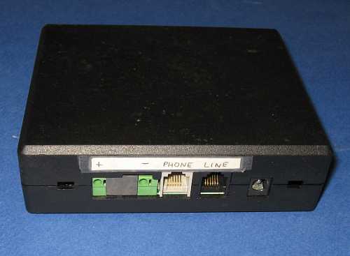
Dial Frequency, Dial Pulse Width, and Line Polarity Tester, Rear View
|
Use of the Tester
To calibrate a dial all that is required is to plug the telephone into the tester and dial a 0.
Okay, its not quite that simple. Set up the tester with a voltmeter connected to the monitor terminals. Rotate the dial to the 0 position. and watch for the yellow READY light. Release the dial and watch the voltmeter. When the dial stops read the voltmeter. A plus voltage indicates the dial has greater than the desired 60% break; a negative voltage indicates less. I don't have a good/bad voltage limit yet, and wont' promise to have one later. Maybe someone can supply me with there findings.
The dial frequency can be tested at any time as it ignores pulse width. Plug the telephone into the tester and dial a 0. If the green LED stays lit, the dial frequency is 9 to 11 pps. Red is either below 9 or above 11 depending upon which LED is lit.
Checking the polarity of a wall outlet is done by pluging one end of a line cord into the tester and the other end into the wall outlet. A crossover line cord is required, not a straight through cord. If the polarity of the wall outlet is correct, the green LED wil light, if not the red LED will light.
How Does It Work
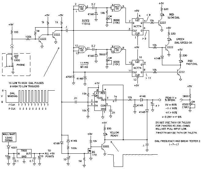
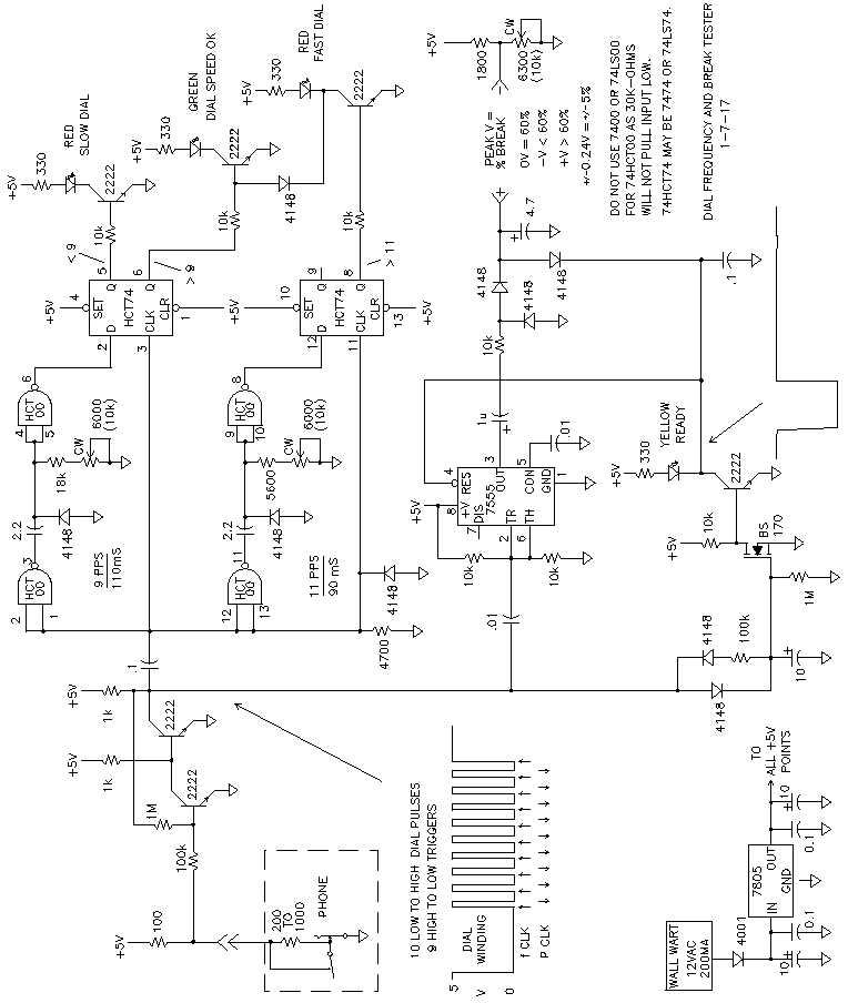
Dial Frequency, Dial Pulse Width, and Line Polarity Tester, Schematic Diagram
|
Dial Frequency Tester
Five volts to the input circuit is enough to supply a logic signal. To mask noise from the mechanical dial switches with high contact resistance that are found in old phones, the two-transistor input buffer has a little feedback in the form of a one-megohm resistor.
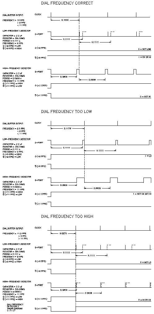
The frequency counter has two detectors - below 9 pps and above 11 pps. Both detectors work the same, only the frequency is different. The 7474 is the detector. Action takes place when the leading edge of each dial pulse goes high. Capacitor coupling of the input removes the dial pulse-width from affecting the detector timing. Each leading edge triggers the 2-NAND-gate timer output low. The RC combination determines how long the output from the timer remains low.
The output from the timer goes to the 7474 D-port. In addition to triggering the timer, the leading edge of each dial pulse also triggers the 7474 to change state depending upon the D-port logic level. The first pulse gives a bogus output, but sets up the detector for the following pulses. On the following clock pulse, if the D-port is low, input frequency is higher than the detector frequency, so the 7474 Q-bar output is high. Conversely, if the D-port is high when the input leading edge occurs, then the 7474 Q output is high.
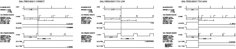
Dial Frequency, Timing Diagram
|
Dial Pulse-Width Tester
A 7555 timer is configured as a bi-stable flip-flop. The threshold and trigger terminals are tied together so the FF changes states on the rising and falling edges of each buffered dial pulse. Capacitors and diodes connected to the 7555 output create a stairstep that rises in 9 pulses to a voltage that is proportional to the pulse width. Measuring the differential between the stairstep voltage and a reference voltage indicates whether the pulse width is above (+V) or below (-V) the desired pulse width.
To reset the flip-flop and zero the stairstep generator, a few diodes and a FET are connected to the dial buffer. When the dial is wound for a test, a capacitor on the gate of the FET is slowly discharged to produce the reset. When the dial is released, the first dial pulse rapidly charges the capacitor to enable the stairstep generator. The RC time constant prevents resetting the generator during dial pulses.
To test a bare dial without the phone, a resistor is needed to keep the stairstep capacitor charged. Without the resistor, the voltage will be discharged as soon as the dial rotation is completed.

Bare Dial Test Cable, Schematic Diagram
|
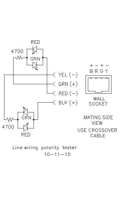
RJ11 and RJ14 Connector Polarity Tester
Some telephones are polarity sensitive due to internal circuitry. For instance, some electret replacement transmitters are polarity sensitive. The drawings below show the wiring from a correctly wired wall outlet to a telephone. Also shown is the wiring in the tester with polarity sensing diodes to make sure all the connections are correct.
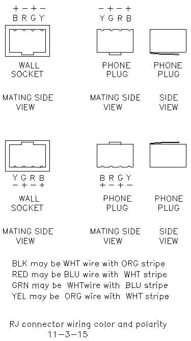
RJ Connector
Wiring Color and Polarity
|
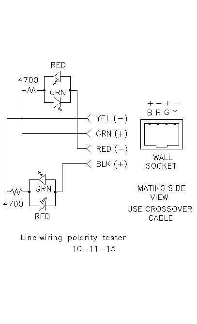
Tester Polarity Checking Circuit
|
Board Layout

Board Layout Diagram
|
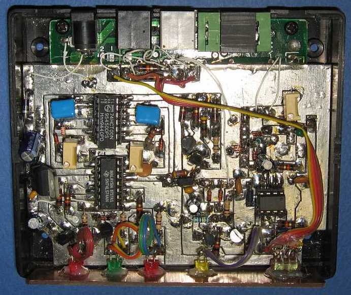
Completed Board
|
Calibration
Frequency
To calibrate using a "golden dial" -one that has been previously calibrated to 10PPS.
Adjust 9-PPS pot for 24000 ohms from the NAND gate input to ground (18k + 6k = 24k).
Adjust 11-PPS pot for 11600 ohms from the NAND gate input to ground (5600 + 6000 = 11600).
Plug in tester power cord.
Plug phone into tester.
Adjust (9-PPS pot for greater than 39000 ohms, maybe start with potentiometer fully CCW (33k + 10k = 43k).
Adjust (11-PPS pot for less than 31900 ohms, maybe start with potentiometer fully CW (27k + 0 = 27k).
Repeatedly dial 0 and adjust the 9-PPS and 11-PPS pots until the OK led lights.
If LO LED is lit, adjust 11-PPS pot CW.
If HI LED is lit, adjust 9-PPS pot CCW.
Decrease 9-PPS pot resistance (CCW) and repeat dial 0.
Keep repeating adjust/dial step until LO LED lights, then rotate pot back 2 turns CW.
Increase 11-PPS pot resistance (CW) and repeat dial 0.
Keep repeating adjust/dial step until HI LED lights, then rotate pot back 2 turns CCW.
OK LED should remain on.
A phone or dial that is known to work correctly can be used if a calibrated dial is not available. However, if the known-good dial used for the "golden dial" is operating an the very edge of the allowable PPS range, the tester will show OK if another dial being tested is 1 PPS outside the acceptable limit.
If an oscilloscope is available, adjust the 9-PPS flip-flop output for a 11ms positive pulse, and adjust the 11-PPS flip-flop output for a 9ms positive pulse.
Pulse Width
Plug digital voltmeter into jacks at rear of tester.
Adjust PW Zero potentiometer for 2. 5 volts from ground to the junction of the 1800-ohm resistor and the pot.
Connect the "golden dial" to the tester using the bare dial cable.
Repeatedly dial 0 and adjust the PW Zero potentiometer for a 0-volt reading on the digital voltmeter.
Copyright Dale Thompson,
31 August 2015 through
last revision on 20 January 2017