Wiring a Stromberg Carlson 1243 with a Western Electric 5H dial for use on a low loop resistance PBX
General
The following is how I wired a beat up SC1243 for use on my home PBX. This 1243 was used in my basement with a headset 51 years ago to talk to my girlfriend (now my wife) and is finally getting the respect it deserves with new paint and correct rewiring.

SC 1243
|
Wiring Source Materials
The SC1243 debuted about 1940 with terminal strips and an anti-sidetone transformer. About 1946 the transformer and terminal strips were replaced by a 200595 network. In 1948 the network was changed to a 205595-B, which is what I have (stamped 348 on baseplate under network, 3rd week, 1948).
Here is a list of the drawings/ documents I have found with discussion of why they do or do not apply to my phone.
SC 205832 Issue No. 1, "Stomberg-Carlson Co. Wiring and Connections for Bridged Ringing for 1243 and 1250 Telephones": This is the correct diagram for my phone. It shows an Automatic Electric dial, but gives instructions for changing to a Western Electric 5H dial. It also gives instructions for wiring changes to use on a low-resistance loop.
BSP C32.506 Issue1 Addendum Issue A 2-7-46C, "Bell System Practices; Station, Installation and Maintenance; Telephone Sets, Stromberg Carlson": Addedum shows wiring to use a Western Electric 5HB dial, but is for an older SC1243 with a 200595 network instead of a 200595-B network.
SC 35830 Issue 3, "Wiring Diagram for No. 1242 & No. 1243 Type Tel.": This shows the standard wiring for a 200595 network. The 200595 has no connections to terminals 13 and 14; the 200595-B has internal connections to 13 and 14.
SC 210951 Issue No. 7, "Stomberg-Carlson Co. Wiring and Connections for Bridged Ringing for 1543W Telephones": This is for a 1543W telephone, but shows the 210649-RA network and illustrates that the network is different from the 200595-B.
Wiring Diagram
I used the Short Loop Version for my home PBX.
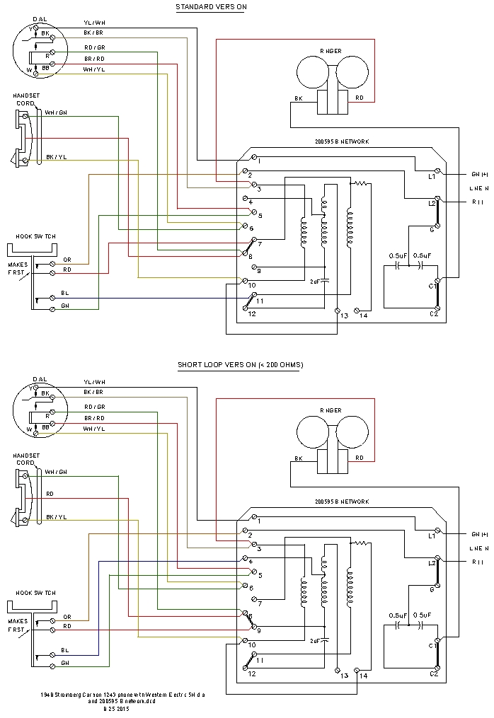
SC 1243 Wiring Diagram
|
Simplified Schematic Diagram of the Stromberg Carlson Anti-Sidetone Network
Following is a set of three drawings that show the Stromberg Carlson anti-sidetone network. The first drawing just shows the short-loop wiring . The second drawing shows the short-loop wiring with the dial and hookswitch in fixed positions and replaced by wires. The third drawing is a reprint of
the antisidetone circuit added to some of my phones. This set of drawings shows that the antisidetone circuit added internally to my old phones that used ringer boxes is very similar to the Stromberg Carlson circuit.
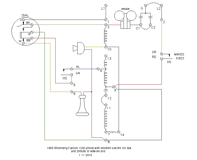
SC 1243 Schematic Diagram
|
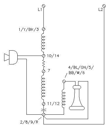
SC 1243 Simplified Schematic Diagram
|
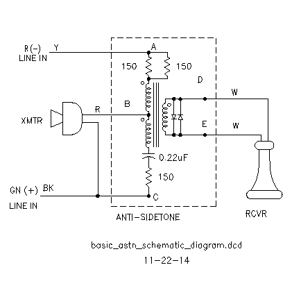
Basic Antisidetone Schematic Diagram
|
Copyright Dale Thompson,
25 August 2015 through
last revision on 11 January 2016