More Arcstarter Drawings

RF Tank Schematic Power Input Schematic Power Simulations Gas Delay Simulation
Welder Modification Controller Module Or Not Return to Arcstarter


Panel Labels

Back to Top


TIG Torch hole diameter was increased to one inch to prevent arcing to metal panel.
 

Panel Dimensions

Back to Top


.
 

RF Tank Schematic

Back to Top


TIG Power Input Schematic

Back to Top


The difference between positive and negative output swings is due to the simulation starting with the ramp capacitor totally discharged. After the first cycle, the waveform is symetrical.

10% Power Simulation

Back to Top


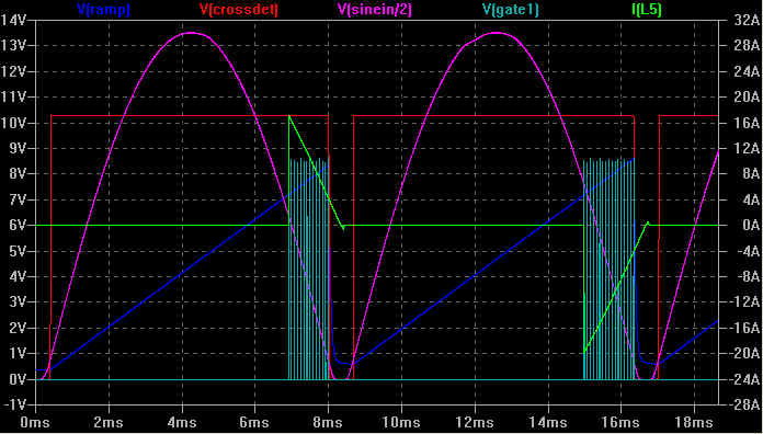
90% Power Simulation
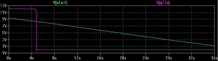
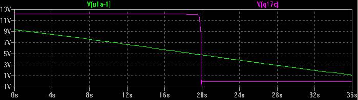
Back to Top

*Solenoid trip point (gas off) =< 2V

Minimum Gas Delay

Back to Top

Maximum Gas Delay

Back to Top

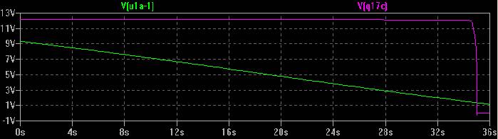
Mid-Setting Gas Delay
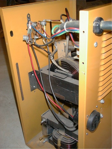
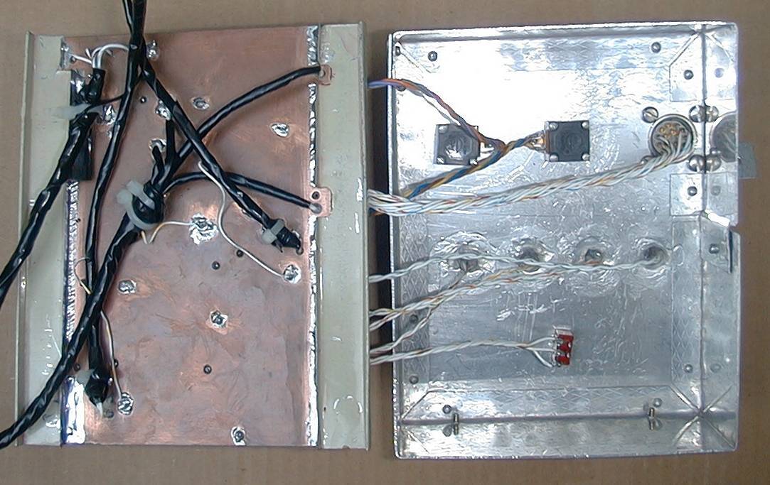
Back to Top


Welder Modification

Back to Top


Controller Module
 
 
.
Back to Top

.
Back to Top

Copyright Dale Thompson.
Last revised: August 07, 2005.