3/16 Scale C&NW Water Tower / Christmas Tree Watering Tank
General
My trains are only set up during Christmas around our tree. In the past, I have used a plastic container to hold tree water, and a siphon tube to transfer the water to the tree holder. The model water tower shown here replaces the plastic container I was using, and looks more appealing than a plastic tub. The tower is a 3/16 scale model of the C&NW tower shown in the 1948 C&NW drawing CE-16730 copyritten by Daniel S. Dawdy and Ribbon Rail Productions on the web site
hpps://cwrr.com/WWW.CyberspaceWorldRailroad/Ribbon Rail Productions. I can't thank these folks enough for hosting these drawings on their site.
Tower History
The Lusk, Wyoming water tower was built in 1886 by the Fremont, Elkhorn, & Missouri Valley (FE&MS) railroad two years after control was aquired by the Chicago and Northwestern (C&NW) railroad. The FE&MS was absorbed into the C&NW in 1903. The C&NW used the FE&MS water tower design as their "standard" watertower in a 1937 drawing CE-9832. In 1948 the design was slightly modified and released jointly with the C&NW controlled Chicago, St. Paul, Minneapolis and Omaha (C.St.P.M.&O.) railway as drawing C.E.-16730. My model tower is scaled from the 1948 version of the C&NW "standard" watertower.
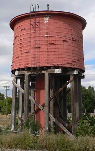
1886 Fremont, Elkhorn, &Missouri Valley railroad water tank in Lusk, Wyoming
|

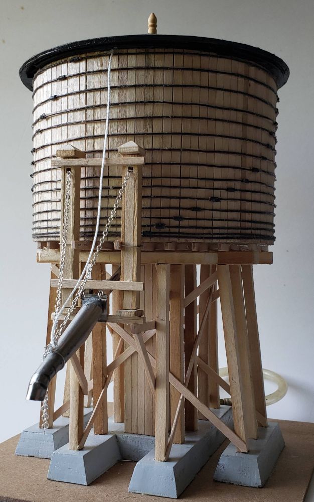
3/16 Scale Model of 1937 Chicago and Northwestern railroad water tank
|
Construction
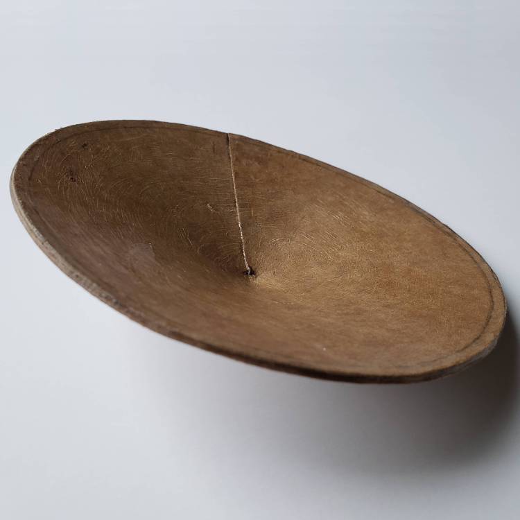
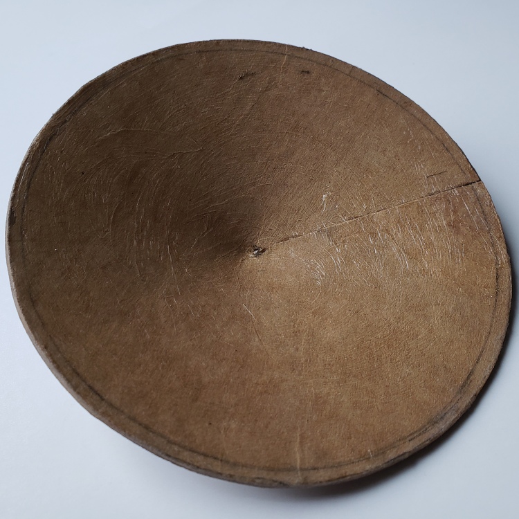
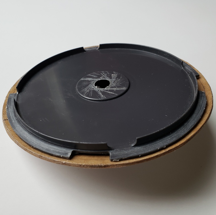
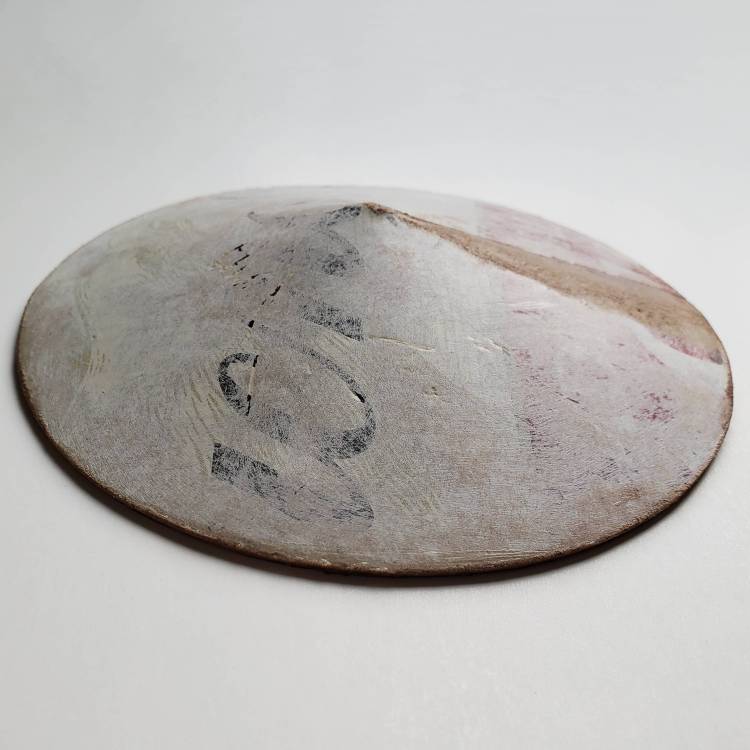
The justification for building this tower was that it would be used for a Christmas tree watering system. There are a few minor deviations from the true 3/16 scale to allow the tower to be used for that purpose. For instance a cut down polypropylene DVD container was used for the water tub. That container results in the tub diameter being 5-1/4 inches in diameter, which would be 28 feet full size instead of 25 feet (the 24 feet tank is actually 24 feet 8 inches in diameter outside). Also, the tower support is about 1/2 inches taller than scale in order to maintain the water level in the tree holder. Changes like these cause additional changes to maintain the look of the original tower.
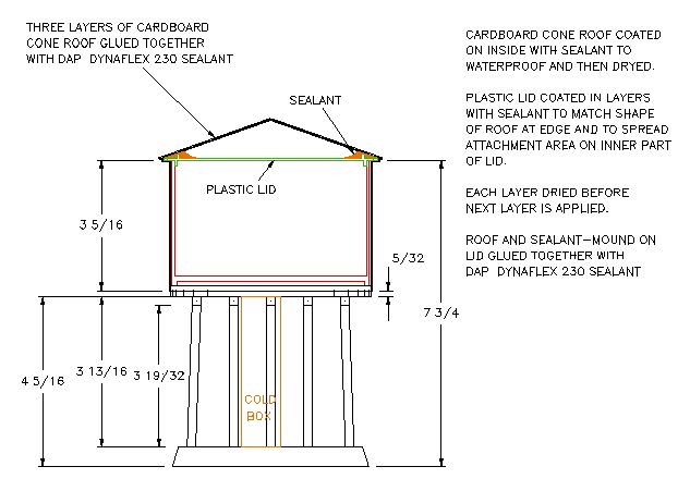
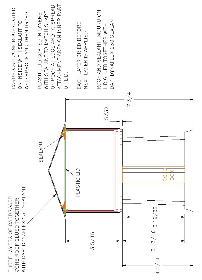
Tank Crosssection
|
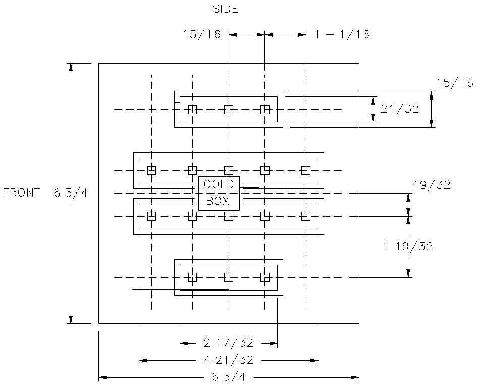
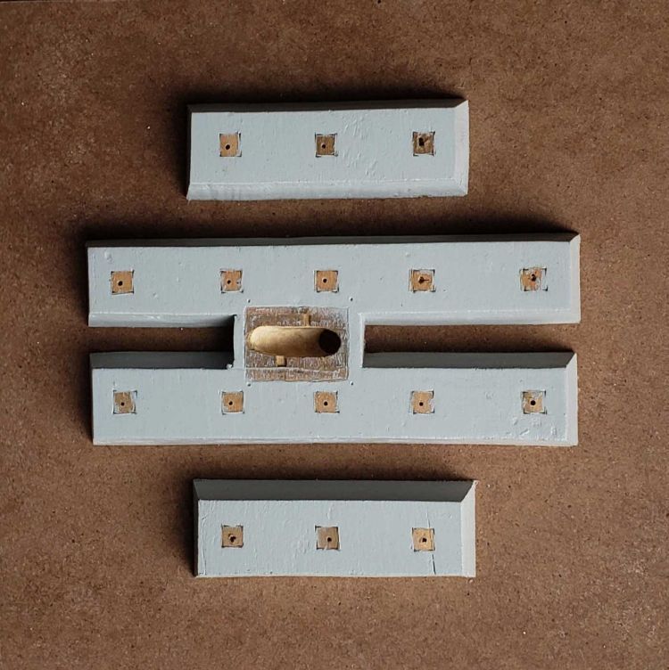
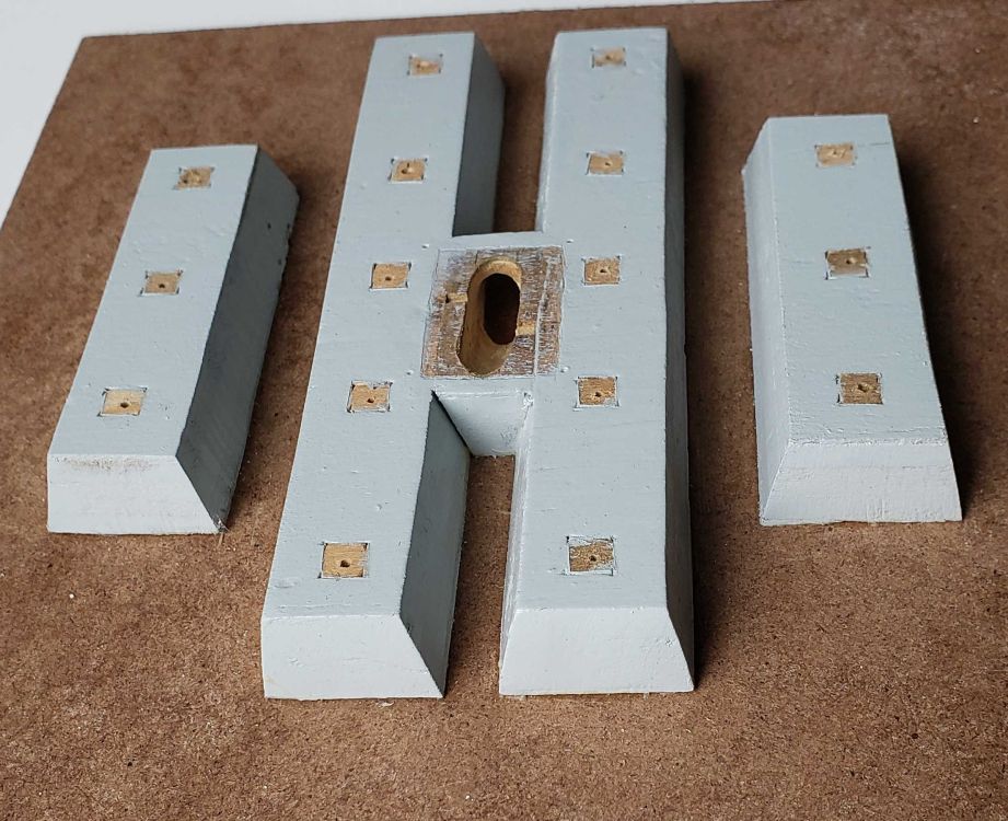
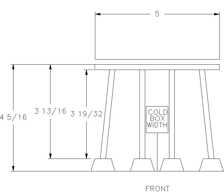
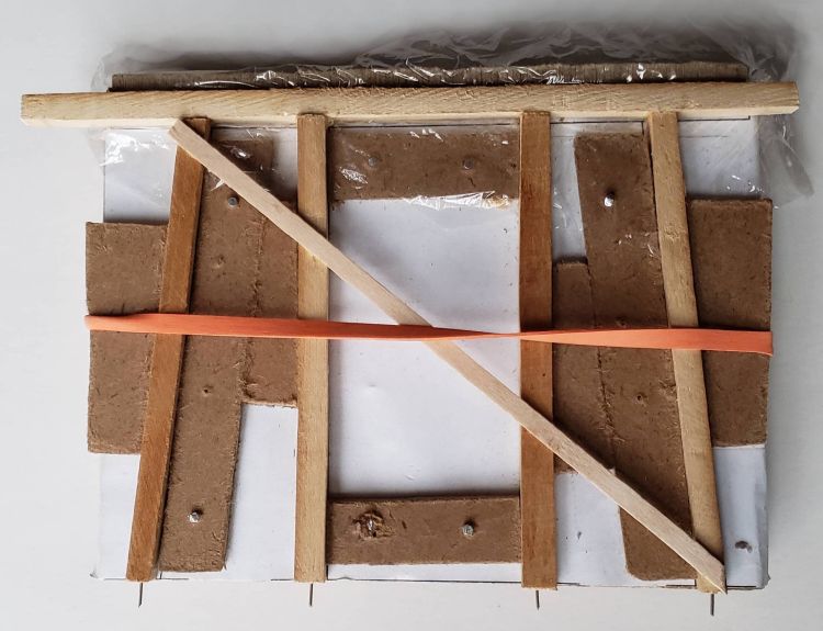
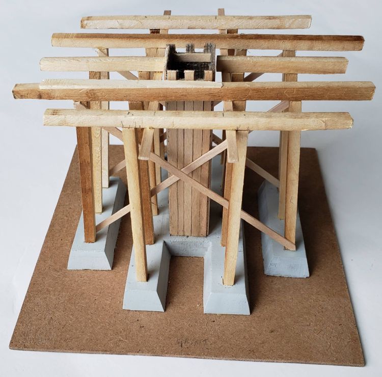
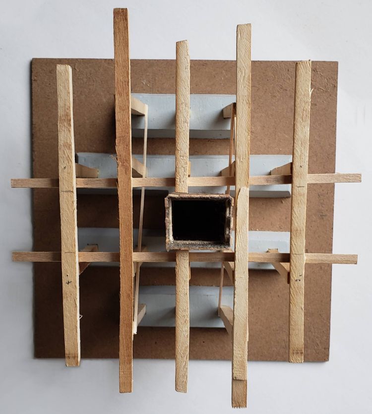
Foundation
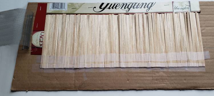
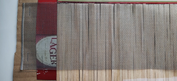
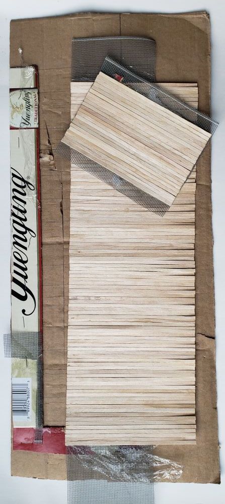
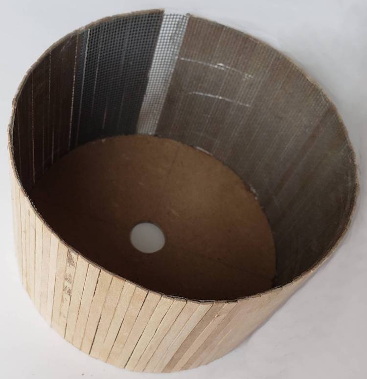
Board Fabric, Posts, and Frost Box
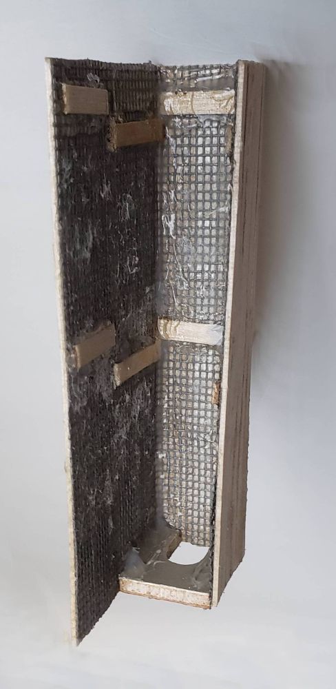
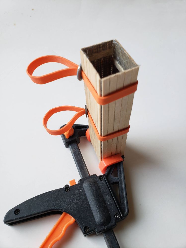
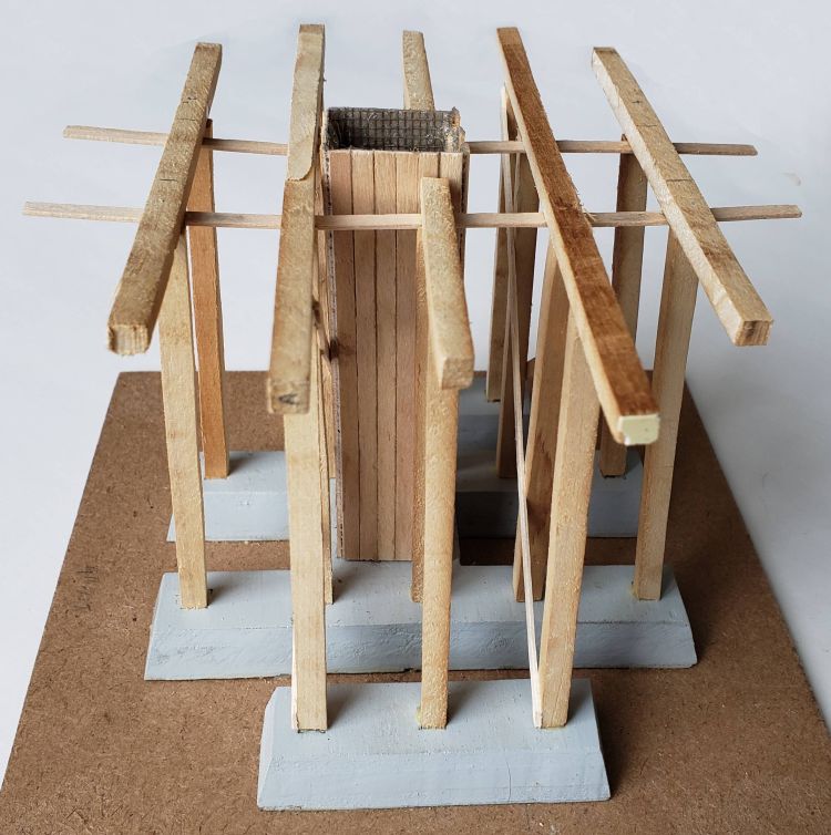
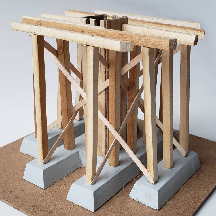
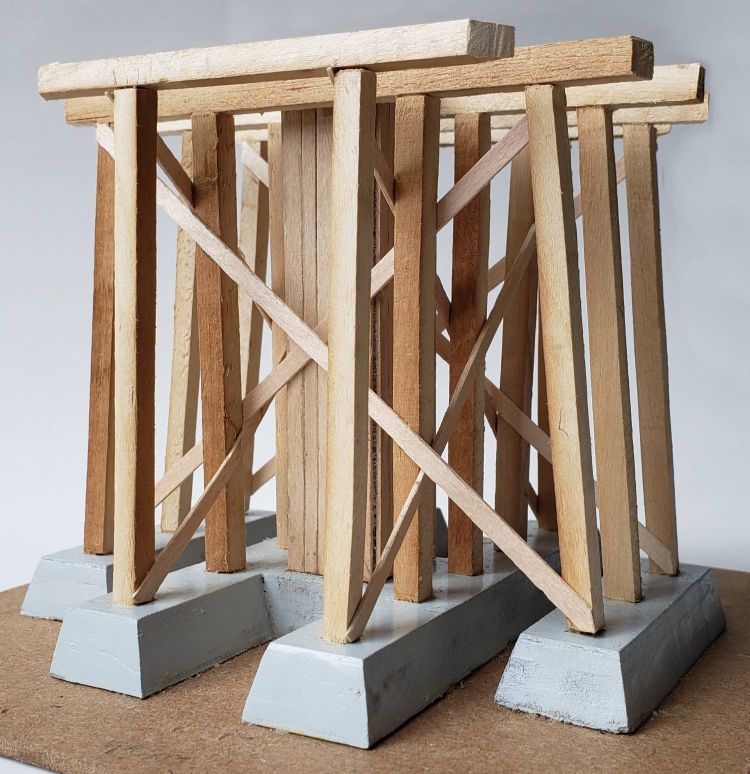
Tower Support
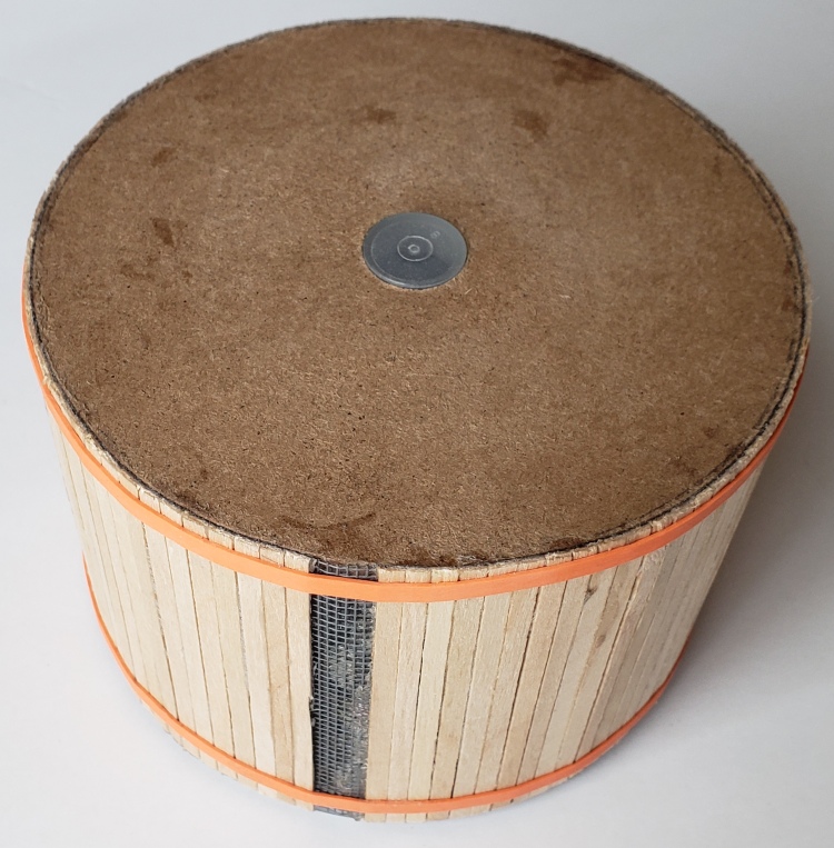
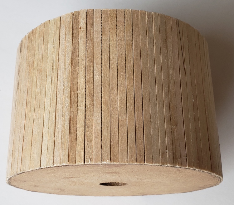
Tank
Roof
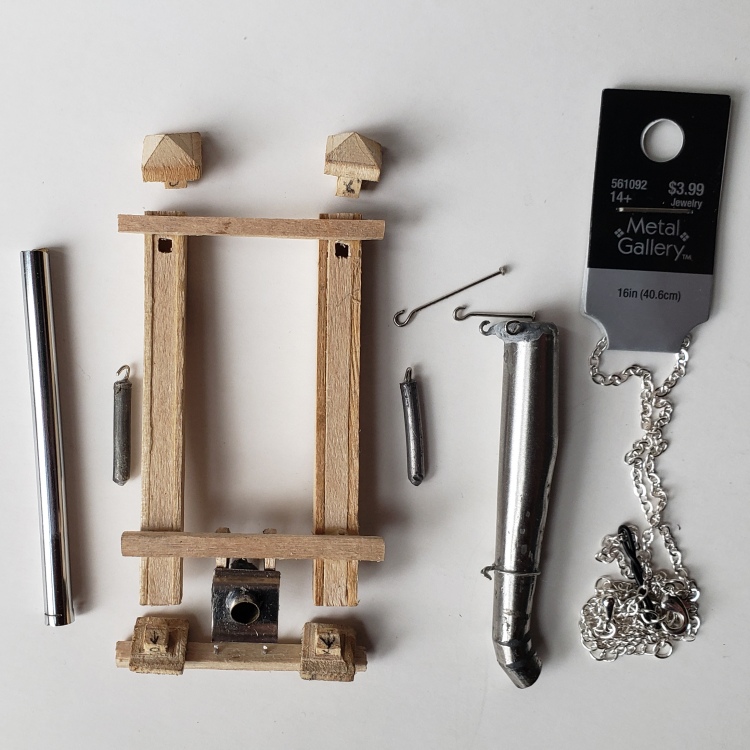
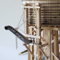
Spout
I saved the hardest for last. The spout had so many small pieces. The counterweight box had to be made of 3/64" wood glued togeter in steps around a plastic form. Then to make the assembly dissasembleable, multiple parts had to be press fit. The weights had to be made from cored solder and equal the weight of the spout. The spout of course was tappered and curved so it was a slow process involving bending, squeezing, glueing, filing, glueing, filing, bending, squeezing, glueing, filing, glueing, filing, ad infinitum.
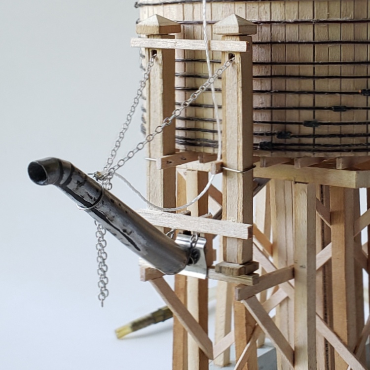
The final spout assembly took two days to mount with removeable strap bolts, but the result is a counterbalanced spout that is moveable up and down like the full-size original.

Counterweight Box
|

Spout Subassemblies
|
Assembled Spout
|
Completed Tower
Photo of Tower Coming after Christmas 2022 was forgotten. Tank was not large enough and now will be used with a warehouse containing water resevoir. Photos are delayed until 2024 Christmas.

Scale C&NW Water Tower / Christmas Tree Watering Tank
|
Copyright Dale Thompson,
14 March 2022 through
last revision on 21 January 2024.
Refer to Copyright notice at thompdale.com.