Mustang Intermittent Windshield Wiper
The dual- or single-speed windshield wipers can be
changed into intermittent wipers without altering any
original switches, wiring, or body parts. This cuircuit
plugs in to the wiper motor and the original wiper
switch. Selection of three different time delays is done
by counting the number of On-Off switch cycles
immediately before the final On selection.
Turn the switch On and the wipers run at normal full
time. Turn the switch On, then Off quickly, then On and
the wipers operate intermittently with a small delay. On,
Off, On, Off, On increases the delay.
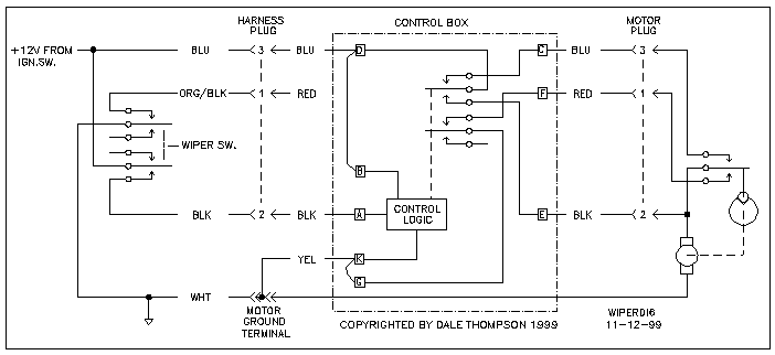
For my 65 Mustang with single speed wipers, the wiper
switch connections as follows:
BLU-- +12V only when ignition switch is on
WHT-- Ground always
ORG/BLK -- Ground only when wiper switch is off (color is
RED after harness plug)
BLK-- +12V only when wiper switch is on
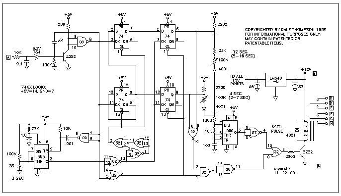
The circuit is very simple. A pulse shaper drives two
7474 counters. With a single turn on of the switch, gate
logic enables the relay that turns on the wiper motor. If
two pulses from the dash switch are received before the
555 ,3-second timer expires, a 2-7 second delay is
introduced before the second 555 timer produces a .6
second turn-on pulse. If three pulses from the dash
switch are received before the 555 ,3-second timer
expires, a 5-18 second delay is introduced before the
second 555 timer produces a .6 second turn-on pulse.
The delay times are set by the two 100k pots to whatever
delay desired between wipes.
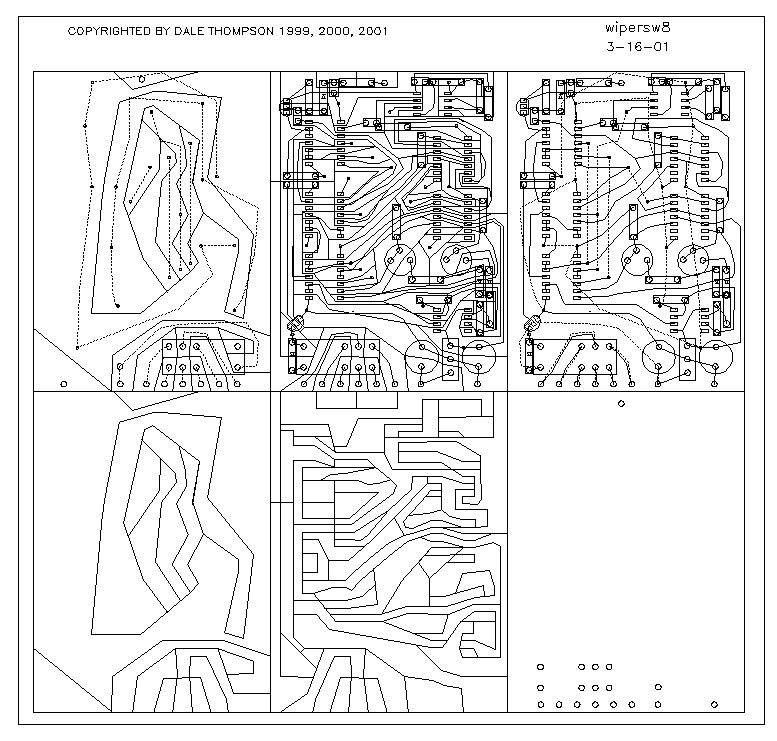
I built the circuit on a circuit board and surface
mounted the components. There is nothing unusual in the
packaging. To keep from butchering the original Mustang I
constructed mating plugs for the motor and switch cable
using epoxy adhesive as molding compound. If the case is
insulated it can be held behind the dash with a velcro
strap. It is better to use a metal case and then insulate
it because the metal case shields the circuit from the
electrical interference present in old Mustangs.
None. It is all original.
Copyright Dale Thompson.
Last revised: October 1, 2006.


