|
|
|
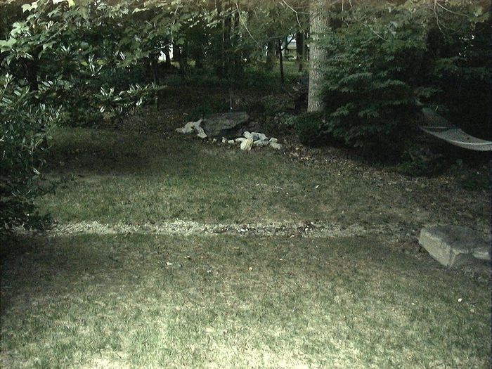
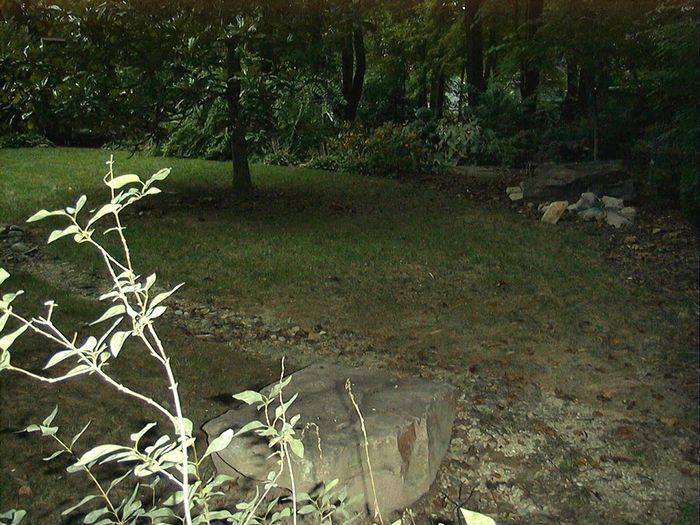
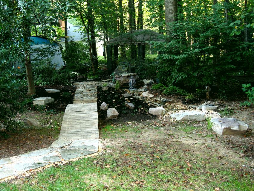
| Beginning |
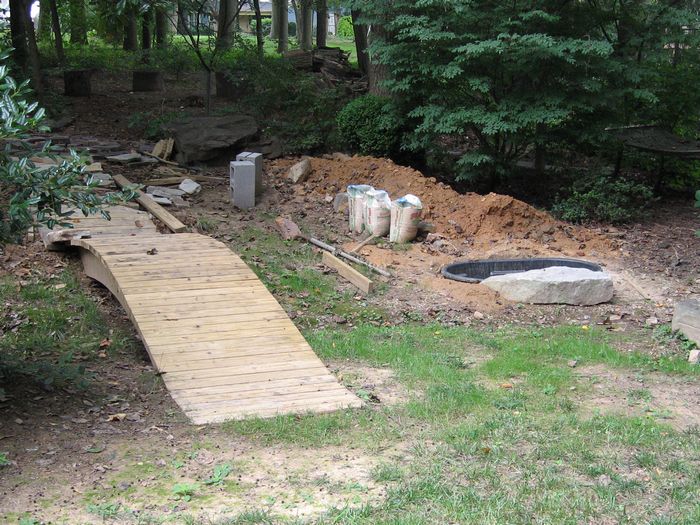
Month One - The Arched Bridge |
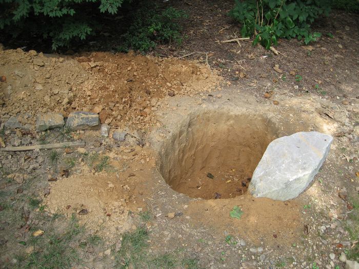
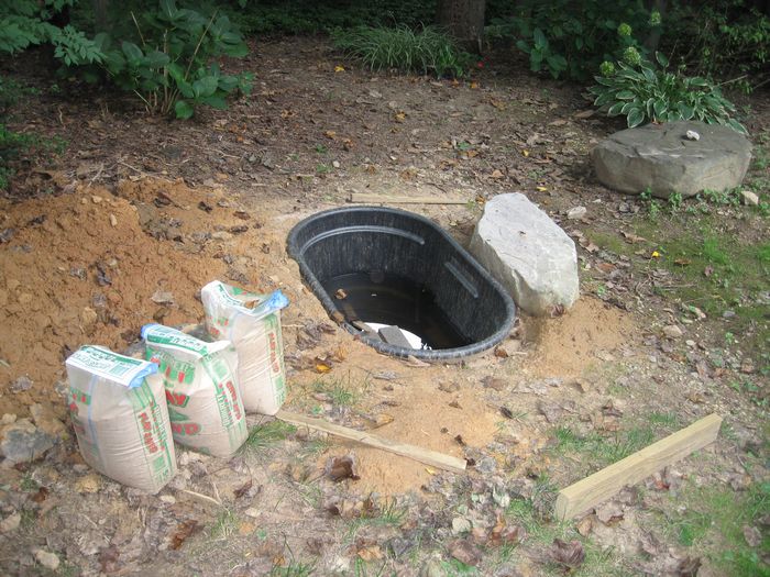
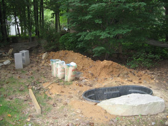
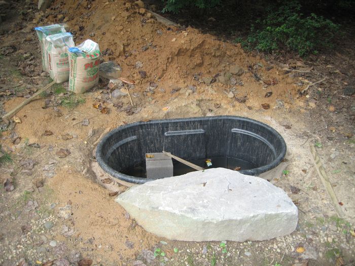
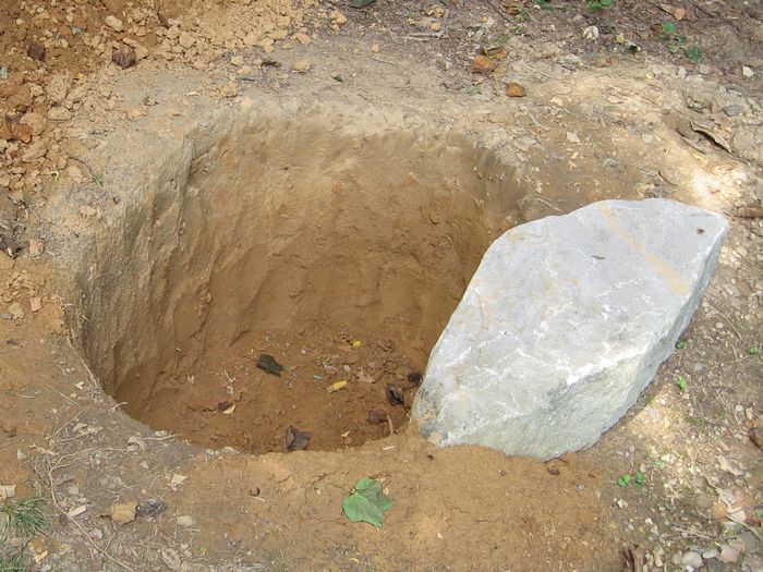
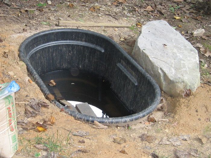
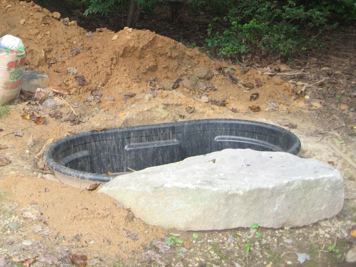
Month Two - Pondless Pond |
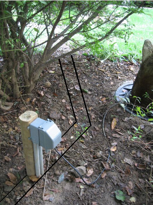
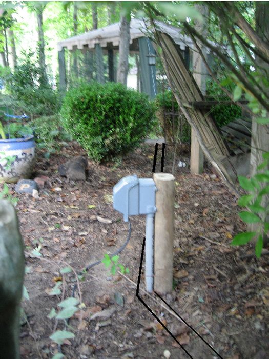
Month Three - Electrical |
|
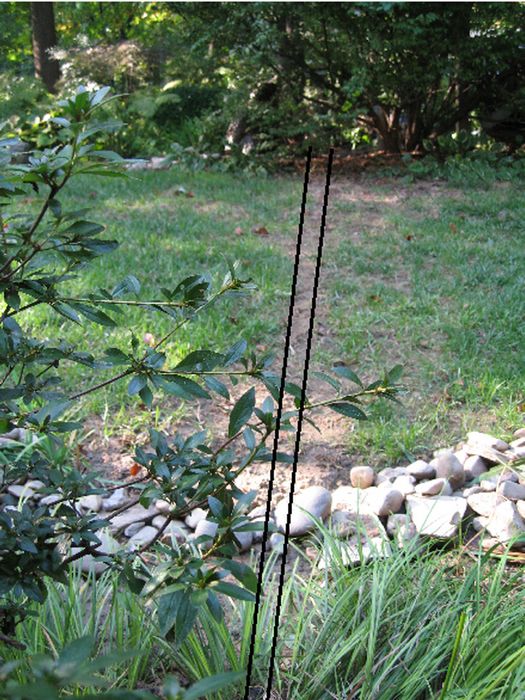
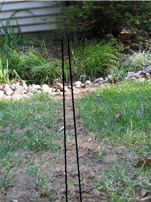
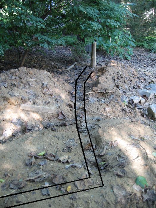
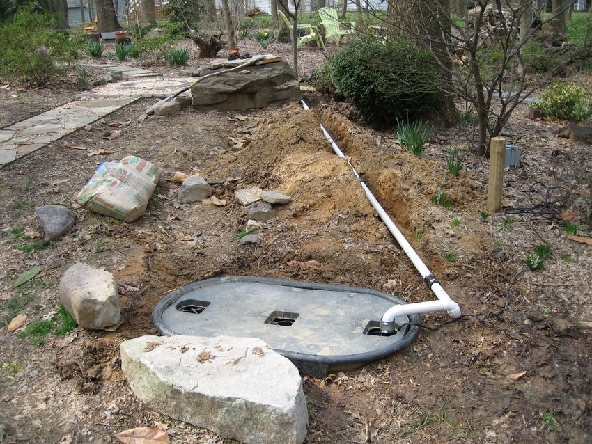
Month Four - Stream Digout |
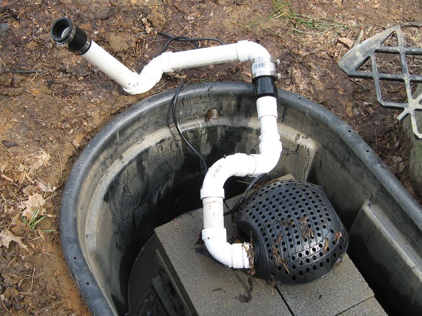
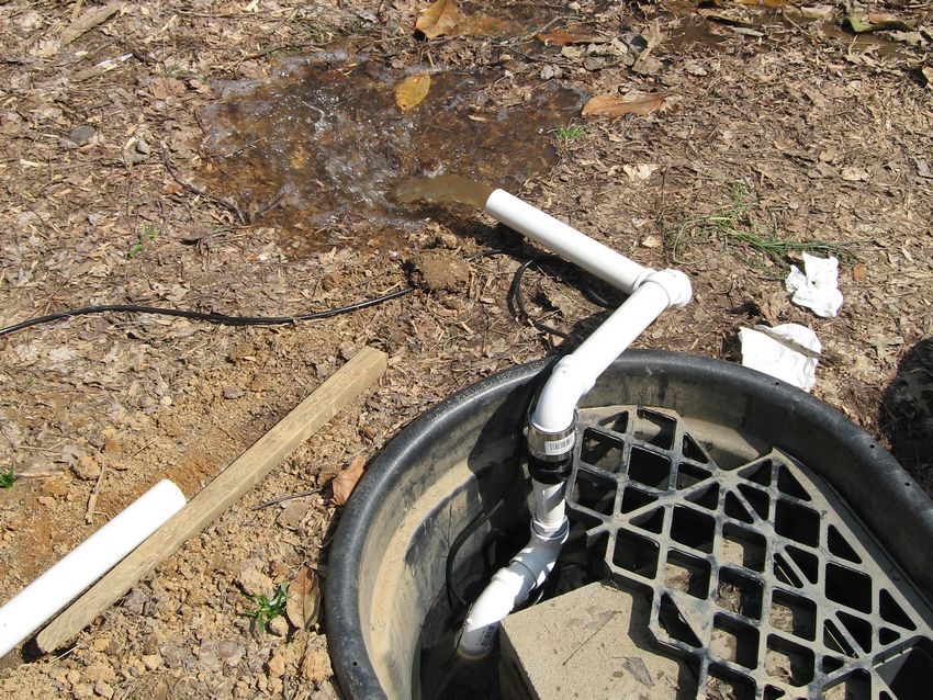
Month Five - Plumbing |
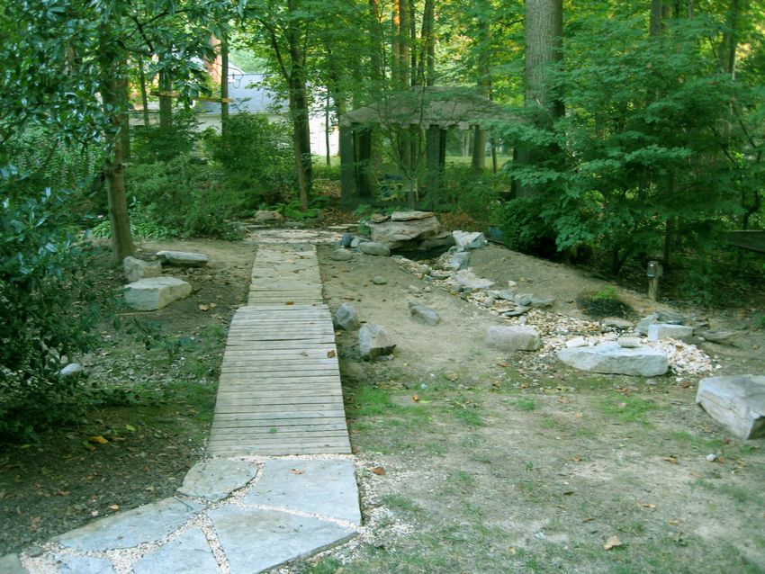
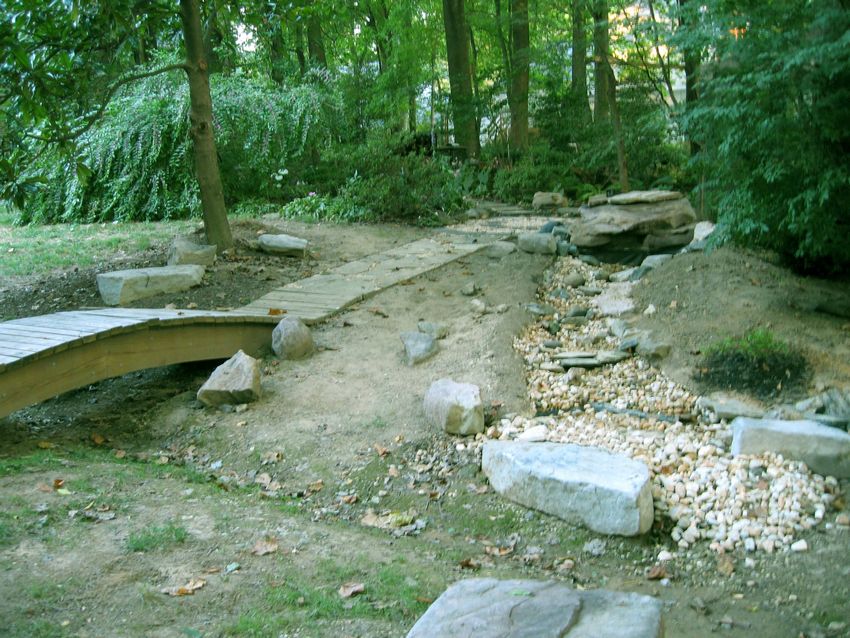
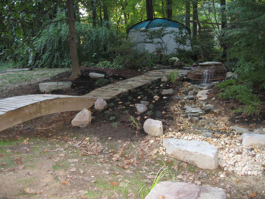
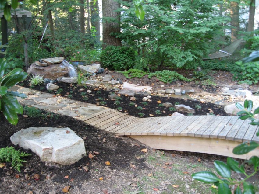
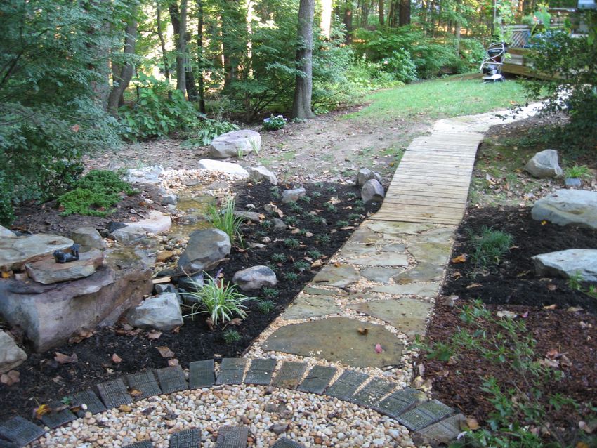
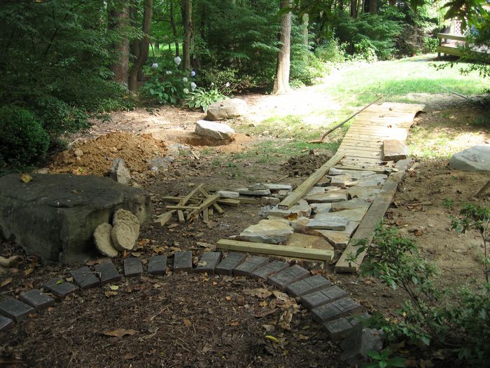
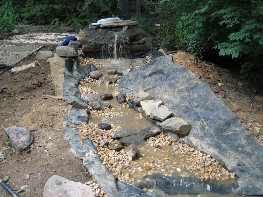
Month Six - The Stream |
Cost |
|
 |
 |
 |
 |
 |
 |
 |
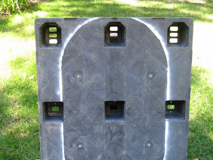
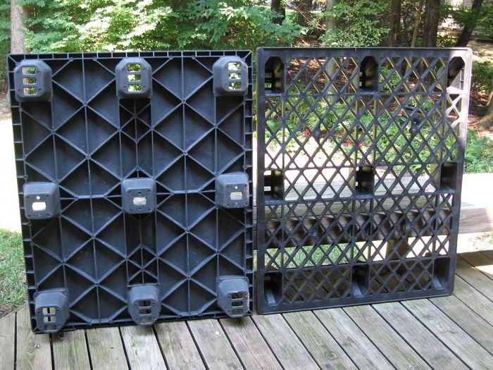 Plastic pallets before cutting |
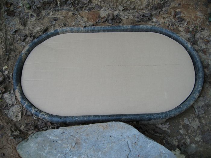 Cardboard template |
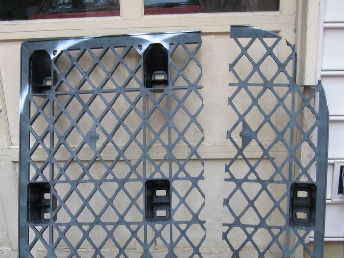 Bottom pallet cut |
 Top pallet marked for cut |
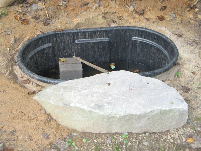
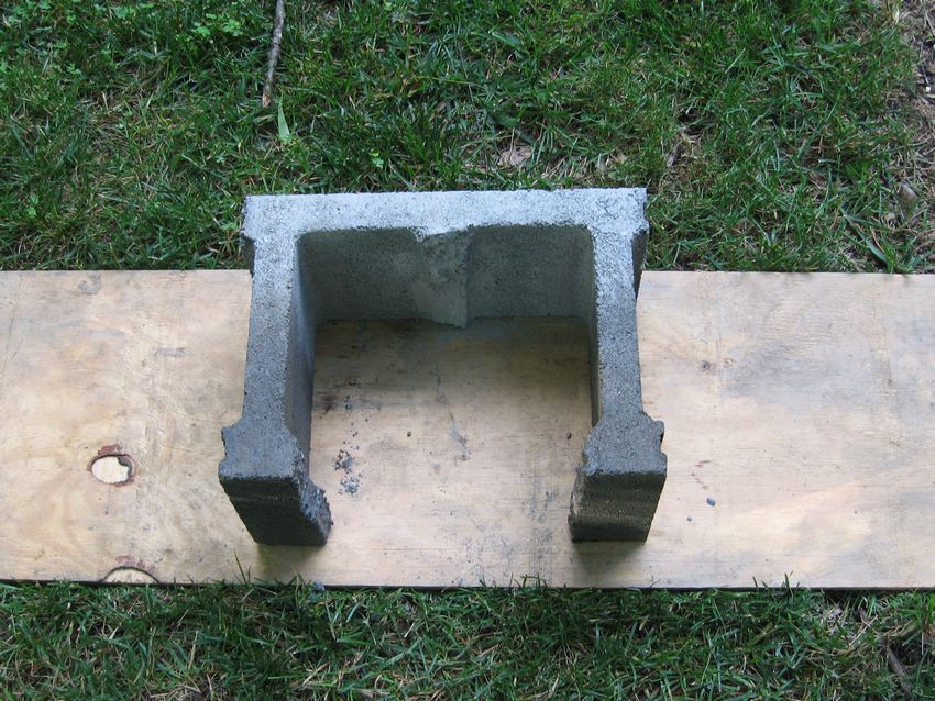
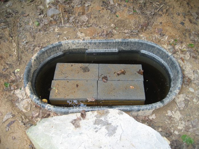 Concrete block pedestal |
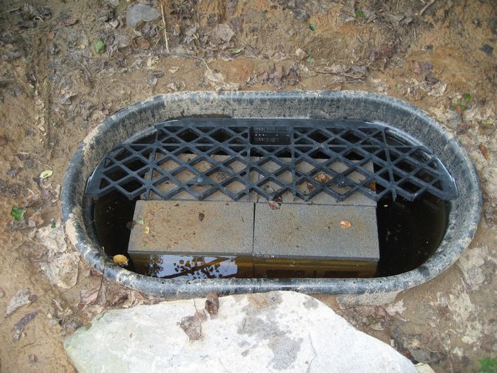 One-half bottom pallet in place |
 Completed bottom pallet |
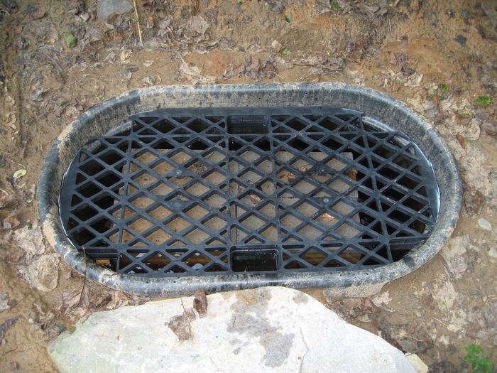
 Top pallet in place |
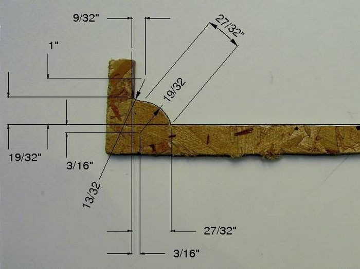 Gauge block |
 Gauge block in use |
 |
 |
 |
 |
 |
 |
 |
 |
 |
 |
 |
 |
 |
 |
|
|
|
|
|
|
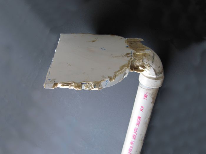 Sheet-vinyl housing glued together and pop riveted to down pipe. |
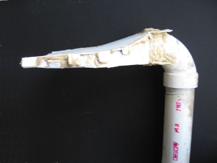 Curve in housing at top distributes water laterally. |
 3/16" x 9" gap equals area of 1-1/2" diameter pipe. |
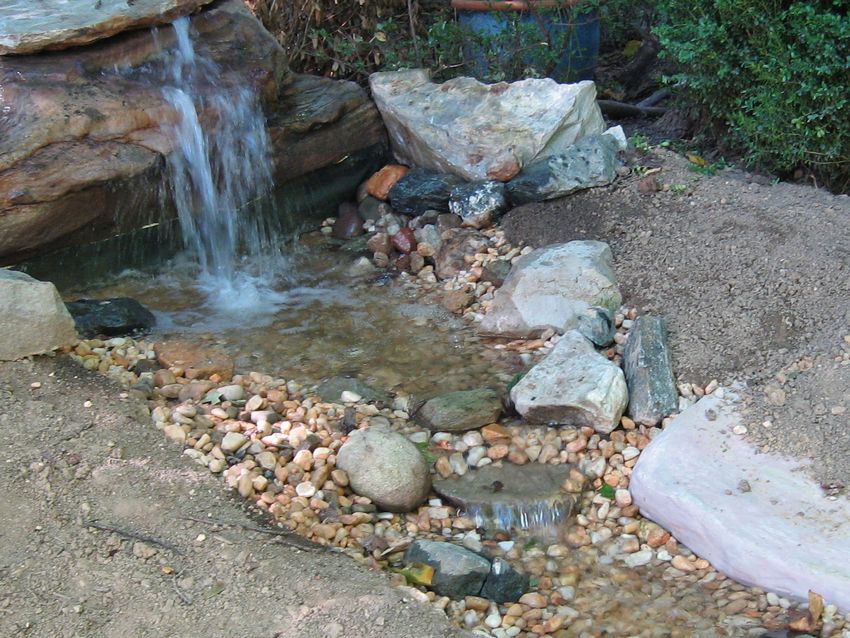
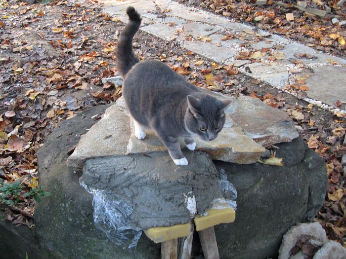 Saran covered boulder with concrete covered spillway housing in place passes inspection. |
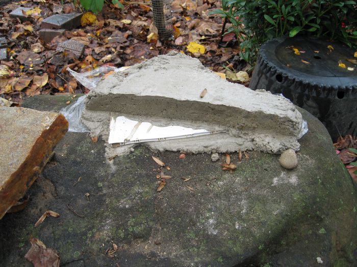 Concrete covered spillway housing in place with flagstone removed. |
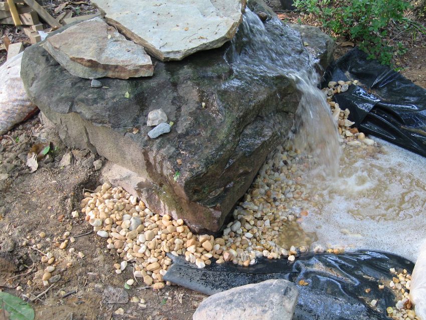
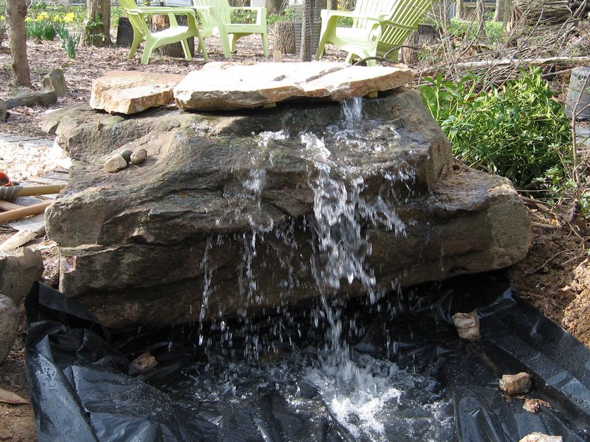 Spillway in operation with water flowing. |
2" gravel mole guard. |

Plastic sheeting flow test. |
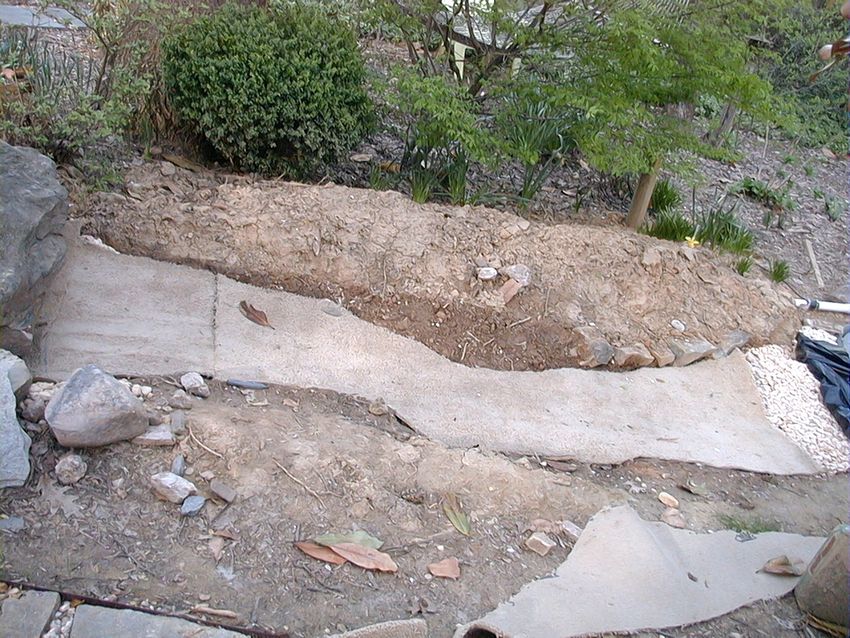
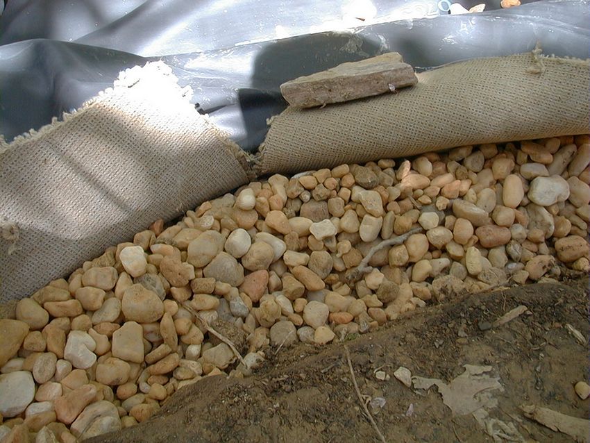
Carpet underlayment over gravel. |
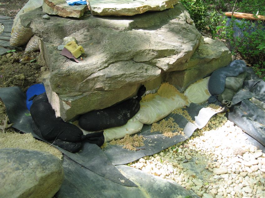
Mounds formed under sides. |
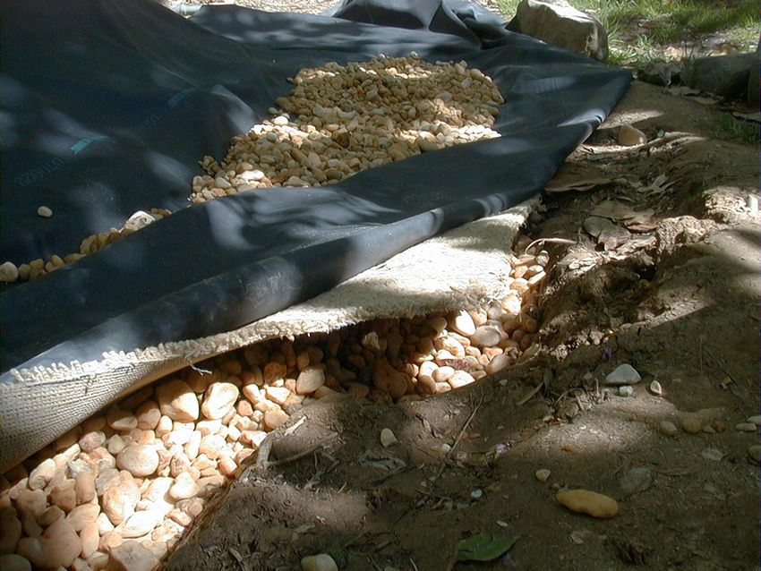
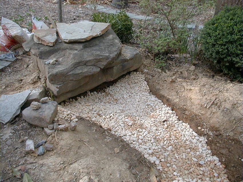
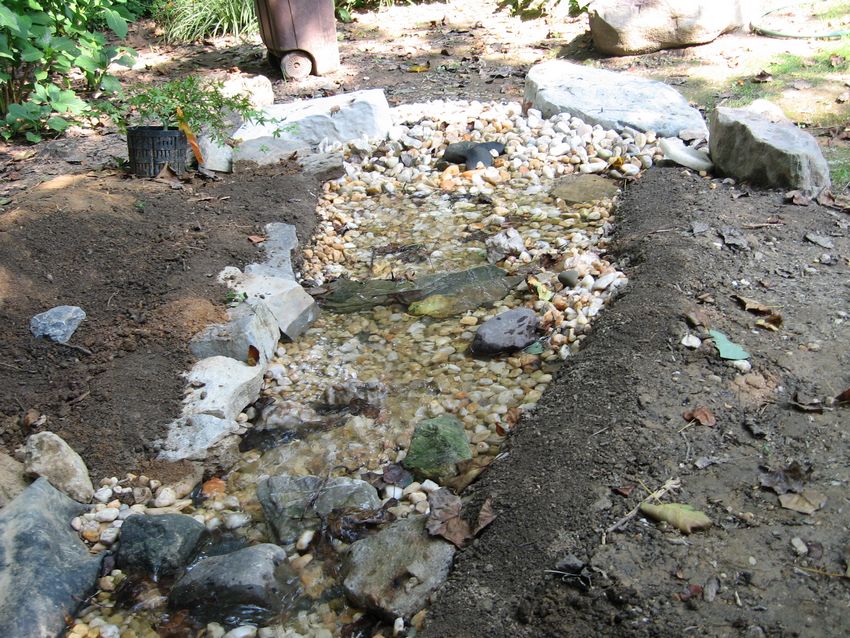
Gravel in center of liner. |
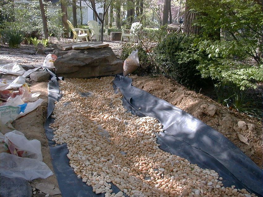
Liner tucked over mounds. |
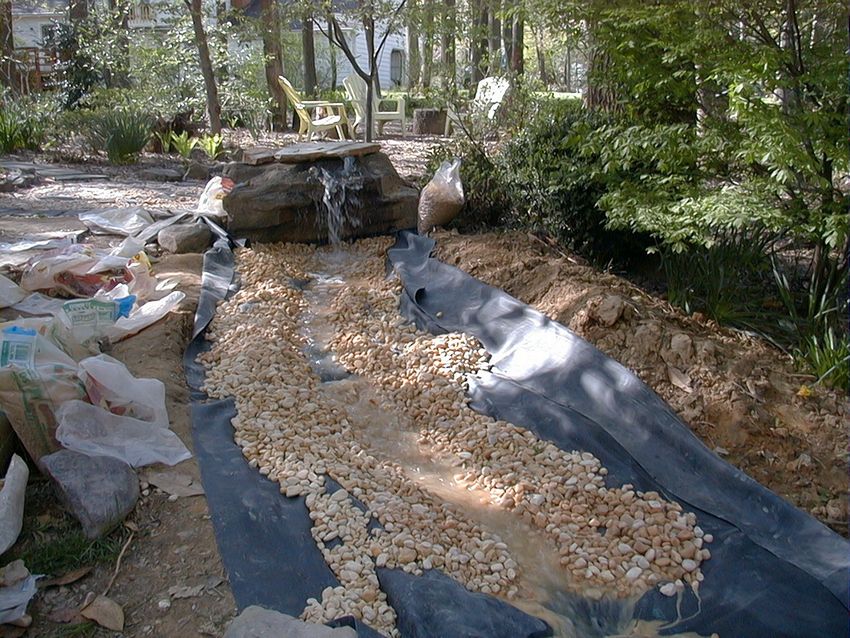
Water test. |
Sandbag falls. |
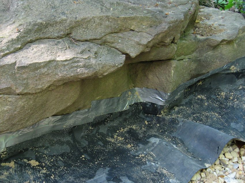
Liner glued and taped to rock. |
Glued, taped, and sandbagged. |
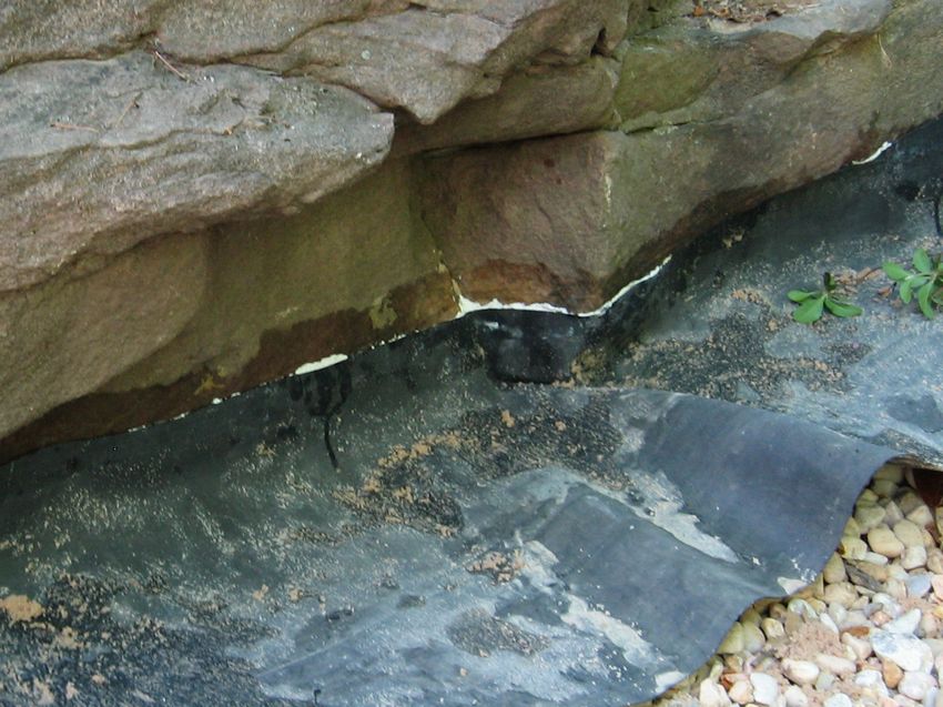
Cured liner flap. |
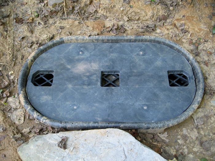
Camoflaged and covered . |
|
|
|
|
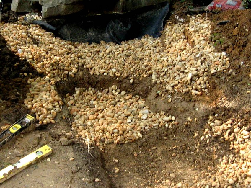
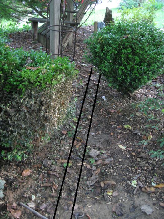
Re-dig for terraces. |

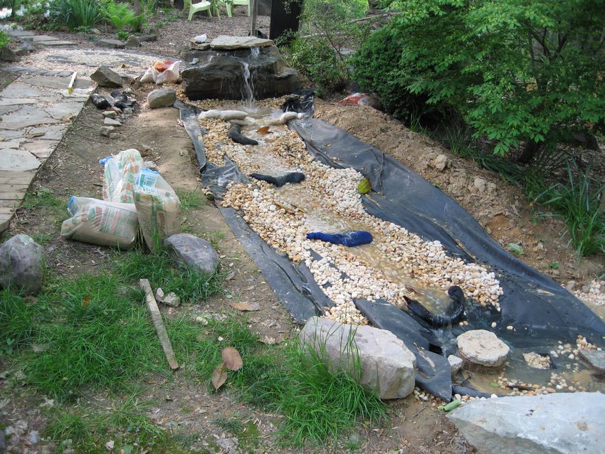
Anti-splash pool. |
Slower flow. |
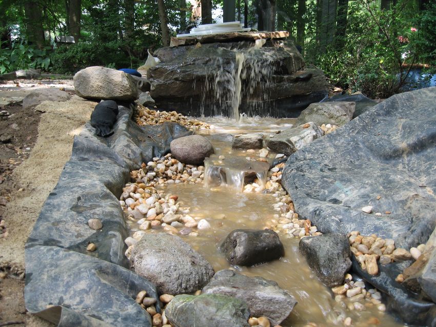
Muddy water falls. |
Stabilized dirt bank. |
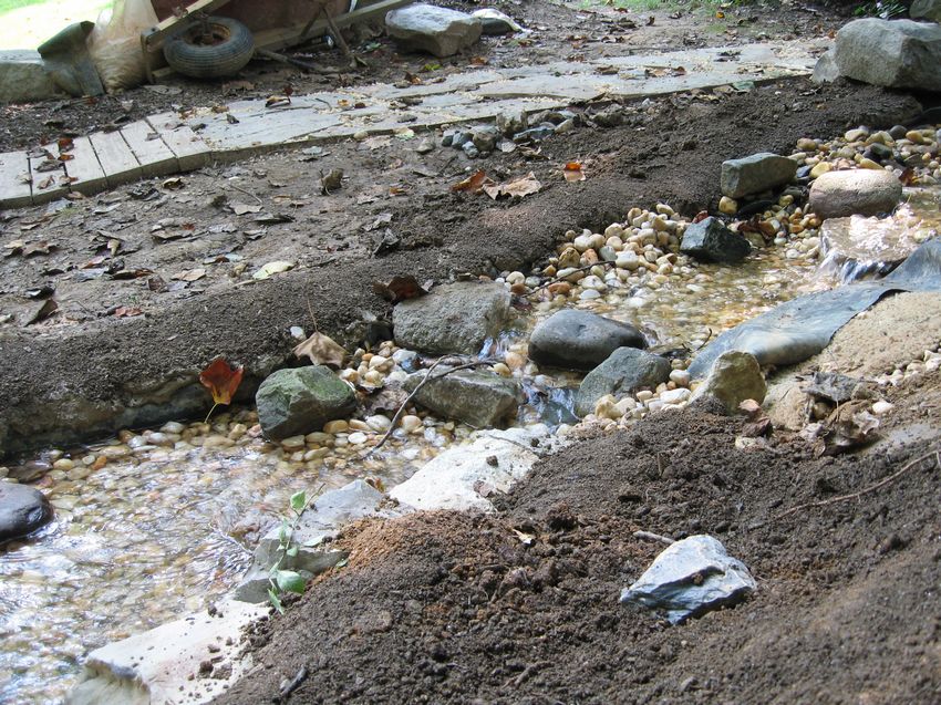
Other side bank. |
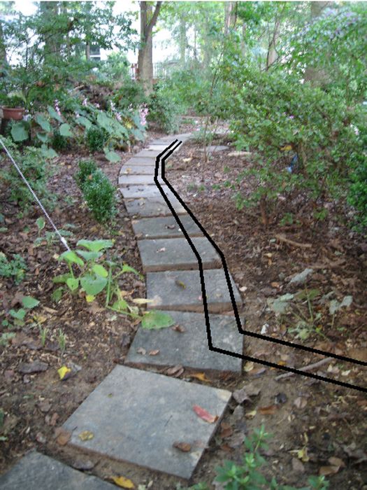
Bottom half done. |
Top half at falls. |

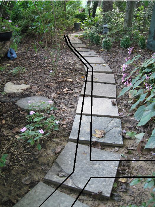
Top half done. |
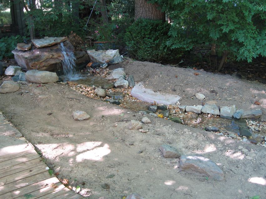
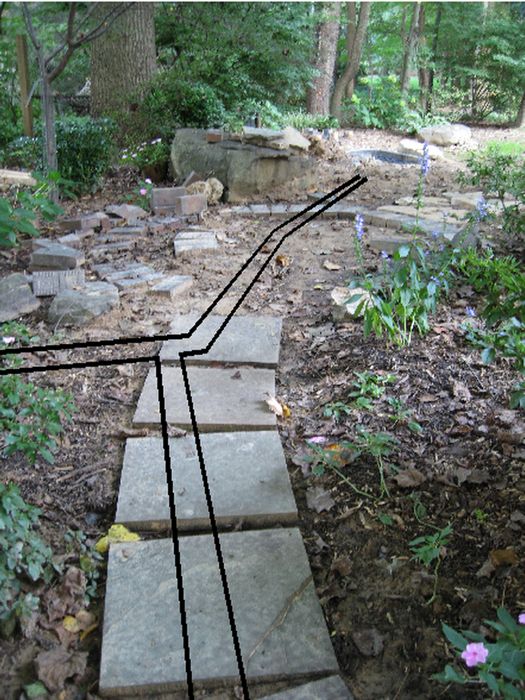
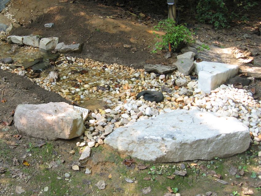
Rock placement done.. |
|
|
|
|
|
|
|
|
|
|
|
|
PONDLESS STREAM MATERIAL LIST
| AREA | DESCRIPTION | QTY | $/PC | $ EXT | VENDOR |
| Stream | Tank | 1 | 69.99 | 69.99 | TSC |
| 8x8x16 block | 7 | 1.31 | 9.17 | Lowes | |
| 4x8x16 block | 3 | 1.06 | 3.18 | Lowes | |
| 12x8x16 block | 1 | 2.40 | 2.40 | Home Depot | |
| CPP110ACM pallet | 1 | 10.60 | 10.60 | Nelson | |
| CPP340 pallet | 1 | 16.50 | 16.50 | Nelson | |
| Sand | 4 | 2.50 | 10.00 | Lowes | |
| Sand | 4 | 2.96 | 11.84 | Lowes | |
| Very Big Rocks | 4 | 994.00 | 994.00 | Vinci Stone | |
| Small stones | 5 | 3.26 | 16.30 | Home Depot | |
| River pebbles | 34 | 3.38 | 114.92 | Home Depot | |
| Gravel, drainage | 1 | 2.96 | 2.96 | Ace | |
| Type-N masonary cement | 1 | 8.88 | 8.88 | Home Depot | |
| Pulverized lime | 1 | 3.88 | 3.88 | Lowes | |
| EDPM liner, 6'x20',45mil | 1 | 78.38 | 78.38 | Harrison Pond | |
| 4-mil plastic test liner | 1 | 8.28 | 8.28 | Home Depot | |
| Underlayment | 1 | 0.00 | 0.00 | Carpet | |
| 3M 5200 Polyurethane Adhesive | 1 | 10.94 | 10.94 | Home depot | |
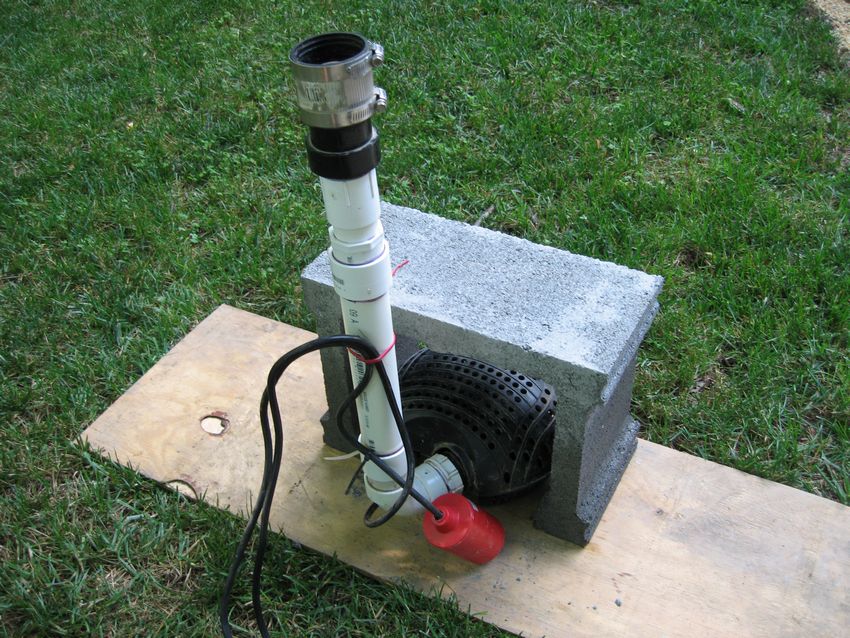
| 3200 GPH Pump | 1 | 119.99 | 119.99 | Harbor Freight | |
| Float Switch | 1 | 27.50 | 27.50 | E-Bay | |
| 1-1/4" / 1-1/4" FSL-NPT coupler | 1 | .58 | .58 | Lowes | |
| 1-1/4" / 1-1/2" FSL-MSL adapter | 1 | .99 | .99 | Lowes | |
| 1-1/4 NPT/1-1/2 SLP backflow valve | 1 | 9.98 | 9.98 | Ace | |
| 1-1/2" / 1-1/2" FSL coupler | 3 | .85 | 2.55 | Lowes | |
| 1-1/2" / 1-1/2" rubber coupler | 1 | 4.37 | 4.37 | Lowes | |
| 1-1/2" / 2" rubber coupler | 1 | 3.91 | 3.91 | Home Depot | 1-1/2" / 1-1/2" FNPT-MSL coupler | 1 | 1.03 | 1.03 | Lowes |
| 1-1/2" DWV long elbow | 2 | 1.86 | 3.72 | Home Depot | |
| 1-1/2" DWV short elbow | 1 | .61 | .61 | Home Depot | |
| 1-1/2" DWV short elbow | 3 | .66 | 1.98 | Lowes | |
| 1-1/2" DWV 45 elbow | 1 | .65 | .65 | Lowes | |
| 1-1/2" DWV 60 elbow | 1 | 1.67 | 1.67 | Lowes | |
| 1-1/2" DWV M-F elbow | 1 | 1.73 | 1.73 | Lowes | |
| 1-1/2 DWV PVC pipe | 2 | 3.34 | 6.68 | Home Depot | |
| Subtotal | 1566.50 | ||||
| Electrical | GCFI receptacle | 1 | 7.97 | 7.97 | Harbor Freight |
| Weatherproof cover | 1 | 3.37 | 3.37 | Home Depot | |
| Siding mini-J-cover | 1 | 6.87 | 6.87 | Home Depot | |
| PVC electrical box | 1 | .47 | .47 | Home Depot | |
| 250 uf 12-2 wire | 1 | 84.97 | 84.97 | Lowes | |
| Outside PVC electrical box | 2 | 4.99 | 9.98 | Lowes | |
| Outside PVC electrical box | 1 | 4.30 | 4.30 | Lowes | |
| Outside PVC elect box cover | 1 | 1.97 | 1.97 | Lowes | |
| Outside in-use outlet cover | 2 | 11.97 | 23.94 | Lowes | |
| PVC elect conduit elbow | 1 | 2.19 | 2.19 | Lowes | |
| PVC conduit | 3 | 1.37 | 4.11 | Lowes | |
| Timer | 1 | 12.97 | 12.97 | Home Depot | |
| 4" x 4" x 4 press treat post | 3 | 2.49 / 8 | 4.98 | Lowes | |
| Trencher rental | 1 | 127.60 | 127.60 | Home Depot | |
| Subtotal | 295.69 | ||||
| Bridge Walk Circle |
2x12x8' ACQ joist | 6 | 10.97 | 65.82 | Lowes |
| 2x4x8' ACQ stud | 20 | 2.82 | 56.40 | Lowes | |
| 3/8-16 carriage bolts, washers, nuts | 24 | .99 | 23.76 | Lowes | |
| Maze spiral hardboard siding nails | 2 | 5.47 | 10.94 | Lowes | |
| 8x8x16 block | 2 | 1.31 | 2.62 | Lowes | |
| Gravel, drainage | 4 | 2.96 | 11.84 | Ace | |
| Flagstone | 1 | 122.75 | 122.75 | Vinci Stone | |
| River pebbles | 12 | 3.38 | 40.18 | Home Depot | |
| Metal edge, 8 | 2 | 9.98 | 19.96 | Lowes | |
| Metal edge, 4 | 1 | 5.98 | 5.98 | Lowes | |
| Metal edge stakes | 8 | 1.07 | 8.56 | Lowes | |
| Subtotal | 368.81 | ||||
| Total | Stream + Electrical + Bridge/Walk/Circle | 2231.00 |