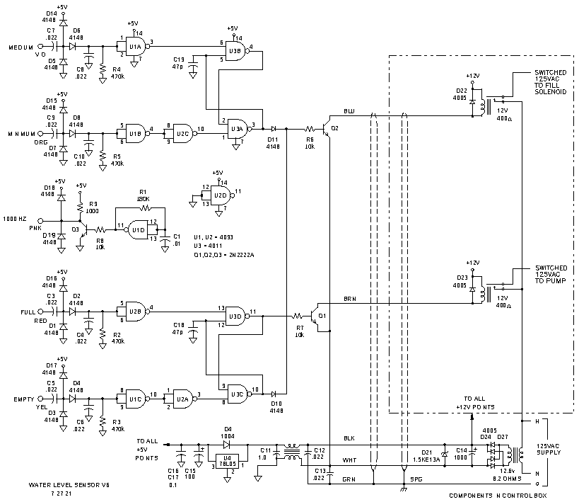
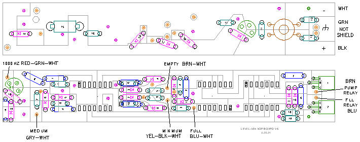
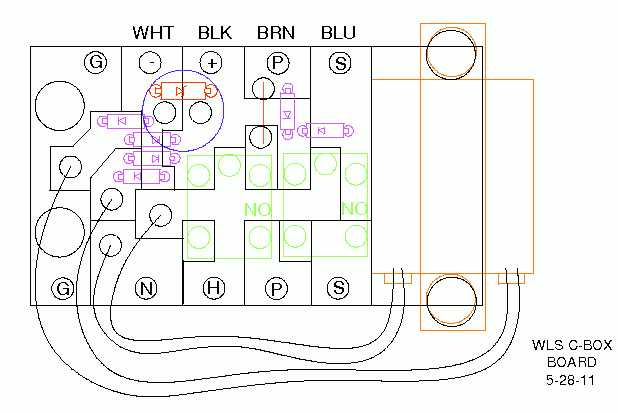
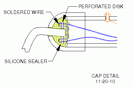
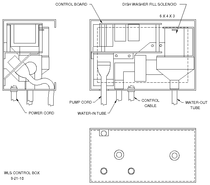
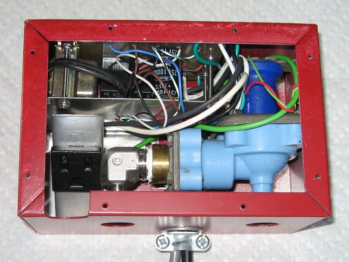
Not a terribly complex circuit, so just a few simple comments.
The cable between the control box and the sensor board is shielded. It connects to ground on the control-box board and to the ground connection on the sensor board . Do not connect this wire to the negative power lead on the sensor board. It is a shield only, and should have only a single point ground connection.
Resistors R1 through R4 are sensitivity resistors and are shown as 464k, but will depend upon the screw size, the screw location, the conductivity of the water, and coupling between wires in the sensor pipe. I simulated this circuit with water at 20k wet and 200k dry, which gave voltages at the gate of 1.5 volts and 3.5 volts respectively with a 5-volt supply. The switch points of the 4093 are 1.5V and 3.5V worse case @25C. Adjust the resistor values to suit your conditions. I tested my water resistance values in a tub of water before I sealed the pipe. Tap water measured 10k at the ends of the wires before board connection. It was too difficult to measure the actual board voltage levels during the test in water. A 29k-Ohm resistor across the FULL terminals produced a logic 0 at U2B-4. A 39k-Ohm did not produce a logic 0 even though the simulation said any resistance below 100k-Ohms should. Simulations are only starting points.
There are quite a few sources for spikes on the 125Vac line: pump moter, fill solenoid, everyday power variations. Spikes have been the major problem with this circuit. The ICs and transistors have been replaced three times due to catastrophic failures. The circuit described here is the second version: the first version is linked
here in case you want to see what was tried.
I used a transient suppressor diode to clamp the supply voltage at less than 18V. I used a 1.5KE13A in my control box because my transformer has slightly less than the normal 12.6V output. My transformer also had a fairly high internal resistance (8.2 ohms) so I used no series resistor in line with the TVS diode. If your transformer is a little beefier, I think a 10-ohm resistor should be added before the diode. I used a common-mode filter to remove transients that might be picked up on the long interconnect cable from the sensor to the control box. Following the common-mode filter, a 5V regulator was used to provide a lot of headroom between the operating voltage and the 18V maximum allowed IC supply voltage. Finally, transient bypass capacitors were used on each IC power input pin.
The final addition was putting 47pF capacitors on the latch output pins, U3A-3 and U3C-10. Switching transients from the MEDIUM/MINIMUM latch U3B/U3A would upset the FULL/EMPTY latch U3D/U3C. The 47 pF capacitors increase the propigation time and mask the switching transients.
One more change. After over a year of trouble-free operation, the oscillator in U1 died. The IC was dead, and a .05uF coupling-capacitor (part of C2 in the old circuit) had a 3500-ohm dc resistance; I can't say what the failure mode actually was. Maybe just a random failure. When I replaced the 4093, I had touble getting the FULL detector to switch, and found the output level from the oscillator to be a little low when the lower-level detectors were in water. To make sure the problem was not due to loading of the IC output, I added a buffer, Q3.
During troubleshooting I changed the value of R7 to 10 kilohms. The original 1500-ohm resistor loaded the output pin and dropped the output voltage to 3.80 volts. This is not a problem and won't damage the 4093, but with a 400-ohm relay, I only needed 30 mA, and a 2N2222A with a gain of 75 at 30 mA works fine with 0.47 mA through a 10-kilohm resistor. Resistor R6 could also be changed to 10 kilohms.
Actually, I did have one other failure in the "year of trouble-free operation" due to bugs: real bugs. A family of ants decided to build a home in the control box. They built across the main AC connection to the circuit board and tripped the GFI feeding the level sensor. During initial troubleshooting, I plugged the sensor into a non-GFI-protected extention cord; boy did those ants come out of there in a hurry, well most of them came out.
After 7 years of smooth operation I had yet another failure of a 4093.
From the beginning, I've had problems that I suspected were voltage spikes. Usually the 4093 cmos logic gates failed. I made numerous changes that got rid of some of the problems, but seemingly, whenever there was a severe thunderstorm I had failures of the logic gates. Once again, the failure occurred after a severe lightening strike. In analyzing the circuit and using simulations I concluded that the problem was due to voltage differential between earth-ground and the ground on the circuit board. The ground on the circuit board is capacitively coupled to the power-line-ground,whereas, the sensor terminals that are in the tank are subjected to spike voltages referenced to true earth-ground. If the true earth-ground potential drops below the power-line-ground potential, which
is possible since the sensor is about a hundred feet away from the house's power-line-ground, then several volts difference is not inconceivable. The ground potential difference could cause the capacitor at the sensor terminal to charge negatively so that the next positive pulse from the oscillator could be added to a charge left on the input capacitor. This would put the potential across the cmos gate a few volts above the 5 volt power supply level which would destroy the input gate. To prevent this I added a diode to each input sensor to clamp the input at the 5 volts power supply voltage. Plots of the spike simulations are shown
here.
In most pondless waterfalls there is a considerable amount of water in the stream bed. This complicates the auto-fill system because the tank cannot be filled completely while there is water in the stream. If it was filled completely, the tank would overflow when the pump was turned off.
By using four water-level sense points, this complication can be overcome. The four sense points are:
FULL - The level in the tank when the pump is off and the stream water has flowed back into the tank ( the water is as high as possible).
MEDIUM - The level in the tank when the amount of water in the flowing stream is subtracted from the FULL tank.
MINIMUM - The level where re-filling the tank is desired to ensure it will reach the MEDIUM level before the EMPTY level is reached.
EMPTY - The level where the pump will shut off. This level is still above the pump inlet and protects the pump.
If there are 75 gallons in the stream when it is operating, and the tank is a 100-gallon tank, then the FULL level is 100 gallons, and the MEDIUM level is 25 gallons.
If 5 gallons of water in the tank is enough to cover the pump inlet, and not have it suck some gulps of air, the 5 gallons is the EMPTY level.
The MINIMUM level is between EMPTY and MEDIUM. If it is too close to MEDIUM, the fill solenoid may oscillate on and off. If it is too low, splashing may cause the EMPTY point to trigger.
The logic of the level sensor is to turn the fill solenoid on at the MINIMUM level and off at the MEDIUM level. If the level gets down to the EMPTY level, the fill solenoid turns on and stays on until the level reaches FULL. The MINIMUM / MEDIUM circuit is ignored in this case. During the filling to the FULL level, the water in the stream has time to drain back into the tank and thus the overflow of the tank due to the tank being full when the stream draining is prevented.
My four sense points are:
FULL - 20 inches.
When the stream water flows back into tank the level will be 20 inches.
This is 3/4-inch above the concrete blocks and about 4-inches below the tank lip.
The extra depth is to allow for rain and allow a safety margin so I don't have to re-make the sensor.
MEDIUM - 11 inches.
The water in the tank will rise 8-3/4 inches if the pump is turned off.
MINIMUM - 8 inches.
This gives a margin of 3 inches above the EMPTY level.
EMPTY - 5 inches.
The top edge of the pump inlet is 3-1/4 inches.

