Klipsch Promedia V.2-400, V4.1, V2.1,
And V5.1 Amplifier Repair
Bash B.A.S.H.
Klipsch, a company famous for high quality speakers, but also infamous for poor quality amplifiers and equally notorious for poor customer support. Seach the web and you will find many posts from people with dead Indigo BASH amplifiers in their Promedia speakers. These people are begging for schematics and component data so they can repair their otherwise wonderful speaker systems. Is that too much to ask, especially when the speaker systems are out of warranty, out of production, and Klipsch refuses to repair them?
Faced with the lack of support from Klipsch, I began tracing the BASH amplifier circuit for my V.2-400. The following schematics are my best effort to document what I found. I have also described design defects I have found and what I am doing to improve them.
Now V2.1, V2.400, V4.1, and V5.1
Evan Shultz spent an amazing amount of time tracing the circuits for his ProMedia V4.1 and V2.1. This tracing included removing some components to check their value and replacing them. If you think this is not an amazing amout of work, you have never tried it.
After generating schematics of the ProMedia V4.1 and V2.1, Evan moved on to the ProMedia V5.1 . Miguel Mejia provided a V5.1, and Evan bought another V5.1 off E-bay. So now we have the complete Promedia line from V2.1 to V5.1, giving you the customer support that Klipsch would never provide.
The rest of this page is the original V2.400 page.
For the V2.1 description and schematics, click here.
For the New Version V2.1 description and schematics, click here.
For the V4.1 description and schematics, click here.
For the V5.1 description and schematics, click here.
Block and Interconnect Diagrams
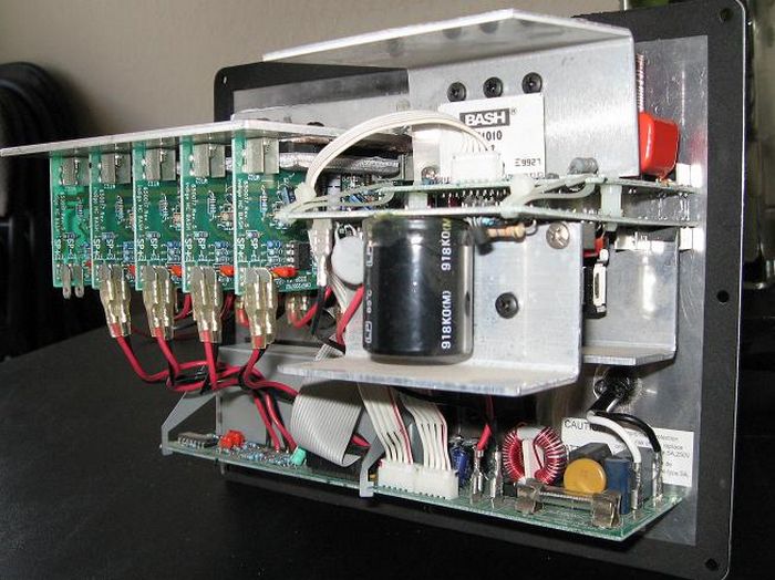
The BASH amplifier is not as complicated as it first appears. AC power of 117 volts is rectified to 156Vdc on the Input-Output board, and then goes to to the DC-to-DC converter. The converter drops the 156Vdc to +/- 30 Vdc that goes to LM340 and LM320 discrete IC regulators on the Input-Output board. From these regulators, the audio IC preamplifier stages get powered up. The converter also supplies a fixed 60-Vdc to what Indigo calls a Digital Converter.
The Digital Converter is the heart of the BASH amplifier. Voltage to the power amplifiers is kept just a few volts above the amplifier's output swing voltage by an audio processor hybrid pulse-width modulating a buck step-down converter. A buck step-down converter operates by applying short pulses of high voltage to an inductor in series with its output load. These pulses flow through the inductor, which builds a magnetic field. The collapse of the magnetic field between pulses keeps the current flowing at a constant rate into its load and back to the inductor through a diode. The voltage across the buck converter's load can be increased or decreased by changing the time the high voltage is applied to the inductor. Unlike the typical buck stepdown converter, in this design, the two FETs in parrallel that switch the high voltage are in the return path.
Block diagram of Indigo BASH amplifier in Klipsch Promedia V2.400
|
Below are the interconnections for the system. The control pod and the satellite speakers shown are separate units; all other connections are internal to the subwoofer box.
Interconnect diagram of Klipsch Promedia V2.400
|
DC-to-DC Converter
Okay, so now we look at the individual pieces of the amplifier. The DC-DC converter is a 2-FET, push-pull oscillator driving a transformer. From the secondary of the transformer rectifiers produce the 60 Vdc and +30/0/-30 Vdc.
Weaknesses in the design are under-rated components. I have calculated the power dissipation of some of these resistors and they appear to be properly rated at 50% of maximum power. However, they have definitely been hot, to the point of scorching the resistor so badly that the color rings can't be read. I have to assume that there is some transient current not accounted for, or that the ambient temperature inside the subwoofer is very high when the system is not being used. This would exceed the power limits at the moment the speakers were first used, which agrees with some of the reports of failure right after begining to use the speakers.
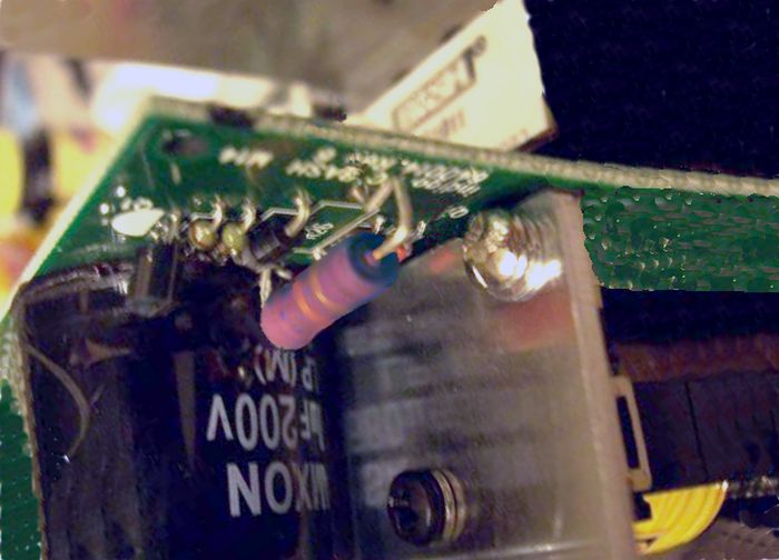
Resistor R27 is 5 ohms and is made by putting two 10-ohm resistors in parallel, one on the top of the pc board, and one on the back of the board. These are under-rated and burn up. I changed these to two, 10-ohm, 5%, 1-watt resistors. I mounted one 10-ohm resistor on the topside of the pc board and one on the bottom. When mounting the resistor on the bottom of the board, wrap the leads of the resistor on the bottom around the leads of the topside resistor. Remember that you may have to remove these resistors someday. If you desire to keep the 1% tolerance you could use four, 20-ohm, 1%, 0.5-watt resistors in parallel.
There are also two 475-ohm, 0.5-watt resistors that are undersized. I think they are R1 and R2, but I have misplaced the paper on which I wrote down the numbers. Use a 6898-ohm, 1%, 0.5-watt resistor on the top side of the pc board with the leads going through the board holes. Then, use a 510-ohm, 5% 1-watt on the bottom of the board. Wrap the leads of the 1-watt resistor around the leads of the 0.5-watt resistor so it is mechanically stable, but easily removable if necessary, then solder both resistors in place. If you can't get the 6898-ohm resistor, a 6810-ohm is okay. Again, want to keep the 1% tolerance? Use four 475-ohm, 0.5-watt resistors. Use two strings of two resistors in series, and put the two strings in parallel. Kind of messy, and the low frequency vibration may fatigue the resistor leads.
The previous resistor changes were not my operational problem. I changed them because of reports of failures and because the resistors were noticeably discolored from excessive heating. My problem was the push-pull oscillator startup circuit. The 47-kilohm resistor R26 was open.
For the 47-kilohm, 2-watt resistor( which should be dissipating .95 watts), I used a 47-kilohm, 5-watt resistor. The lead diameter of a 5-watt resistor is the same as the 2-watt resistor and passes through the holes in the pc board. I put the resistor on the bottomside of the pc board. There is nothing above the bottom of the board so mounting it there gives better airflow with no mechanical interference.
Schematic diagram of DC to DC Converter
|
Digital Converter
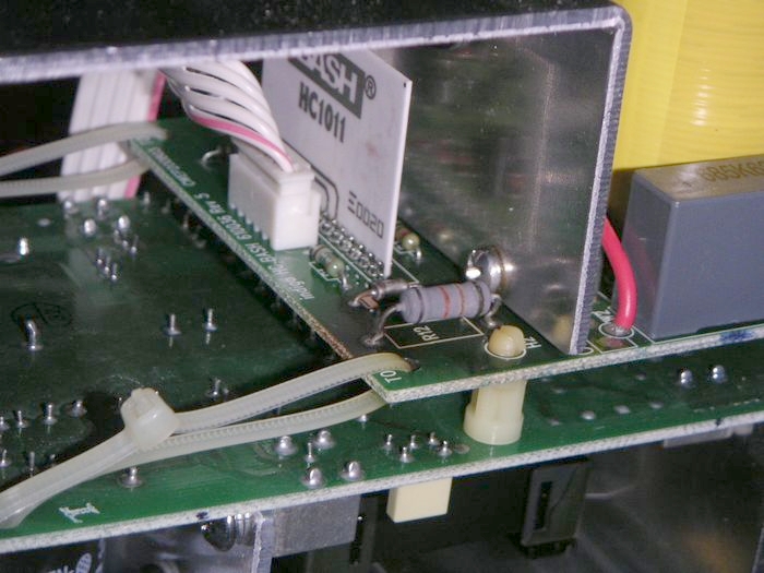
The final weak spot, reported by others, but not failed on my amplifier yet, was the 680-ohm, 2-watt resistor R12. Resistor R12 looks like a 1-watt-at-25 degrees-C rated resistor , but it is dissipating 1.1 watts at a somewhat higher temperature, so, it must be a 2-watt resistor. This is still a little above the normal design guideline of 50% of rated power at normal operating temperature.
I used a 680-ohm, 5%, 5-watt resistor on the top of the pc board. I also used the resistor lead to parallel the pc board track from the resistor to Zener diode Z1. This track is heavily loaded and is heated by the power disipated by R12. It has been reported as a failure area by others, and was looking very bad on my amplifier. Bring the lead of the resistor through the pc board hole and wrap it around the tip of the lead from Z1 that protrudes from the bottom of the pc board. Then solder it, of course.
Schematic diagram of Digital Converter
|
Indigo BASH HC1010 Module
The HC1010 or HC1011 Module uses a UC3842A controller IC to drive the FETs in the Digital Converter in response to the demands fed to it by the Amplifier Board's AMP-LEVEL signal. A current threshold is established in the UC3842A by the AMP-LEVEL signal. Feedback of the rail voltage to the Amplifier Board at FB-IN reduces the threshold when the rail votage approaches the established point. In the UC3842A, the threshold sets the point where the I-SENSE voltage from the Digital Converter FET source resistor will cause the UC3842A to cut off the DRIVE output to the FET gates. Switching off the FET gate drive determines the pulse width of the buck converter in the Digital Converter, and in turn establishes the Amplifier Board rail voltage.
An AMP-OC circuit is incorporated in the Module that reduces the rail voltage if excessive current is being drawn by any of the Amplifier Boards.
For a more detailed description of the Module operation click here.

Schematic diagram of Indigo BASH HC1010 / HC1011 Module
|
Module Versions
Some of the late V2-400 units may have used an HC1011 module instead of the HC1010, or perhaps some of the early V4.1 units used the HC1010. The change over date is not known.
I-O Board
I did not have a problem with the I-O Board, so I only traced the voltage regulator portion of it. David Roberts donated a V2-400 unit and Evan Shultz traced the circuits (He actually traced all the circuits in the V2-400, so the info on this page should be pretty accurate.)
It appears that the V2-400 and the V4.1 I-O boards are the same. On the unit that Evan traced, R1 was left off of the board and R17 was 1000 ohms. However, on my unit, the resistors are as shown on the schematic.
Amplifier Boards
Like the I-O Board, I did not have a problem in the Amplifier Boards, and did not trace the circuit. Evan Shultz traced the circuits in the unit donated by David Roberts, and now we have a schematic.
It appears that the V2-400 and the V4.1 amplifier circuits are also nearly the same. The printed-circuit board for the V2-400 and the V4.1 board are different and use different reference designators.

Amplifier Board Schematic Diagram
|
Hopefully, this data will help someone get their Klipsch Promedia speakers speaking again. I have tried to accurately trace and record the circuits in the BASH ampifier, but I have found some errors when I double-checked circuits. Undoubtedly, there are other errors in my tracing that I did not find. If you find an error, if you know the value or designator for an unidentified component on the schematics, if you have traced one of the other boards and want to share it, or if you have troubleshooting tips that you think will help, e-mail me at
thompdale@hotmail.com .
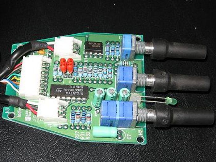
Control Pod
Klipsch first marketed the V.2-400, then the ProMedia 4.1, and still later let loose with the 'CP-1' released as an upgrade to the prevous two control pods. This implies the existence of three different control modules all roughly interchangeable, though probably not equivalent. And none of them, apparently, for sale. My pod is very simple, having only two audio input cables, one 8-pin DIN cable, 3 pot knobs (reading left to right: 'Subwoofer, Surround, and MainVolume')' and a green led. Its passive component count is less than the V4.1 Pod Evan Shultz describes.
Tom Hydorn traced the circuits on his V2-400 Contol Pod and supplied the information for an early version Pod. Evan Shultz did the same for his Pod and supplied the component reference designators shown on the schematic below. The component reference designators may not be the same for all versions.
Control Pod Schematic Diagram
|
DIN Connector
The DIN plug for the V2.400 and the V4.1 is an 8-pin, 45-degree-arc-per-pin, 270-degree-pin-arc-total plug. Its DIN specification is 45326 (obsolete specification replaced by IEC/DIN EN60130-9). When looking for a replacement, make sure it is the 270-degree version. Do not try to use the 8-pin plug with four, 45-degree arcs and two 41-degree arcs for a total pin arc of 262 degrees. The pin pattern in the 270-degree plug is a circle; the one in the 262-degree plug is horseshoe shaped.
The diagram below for the V4.1 DIN plug was taken from Klipsch forum postings that I believe is correct. I have not verified it, but I have not found any posts disputing its accuracy. The pin numbers on these diagrams don't conform to the DIN standard 45326.
The diagram for the V2.400 DIN plug comes from my own tracing of the wires on my plug. My control pod is the original unit, not the CP-1. I chose to identify the pins by using the pin numbers on the control pod circuit board connector.
These diagrams are shown looking at the mating side of the plug pins and not the soldered side.
DIN Connector Wiring Diagram
|
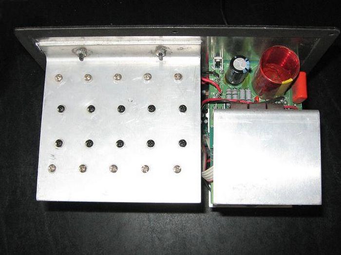
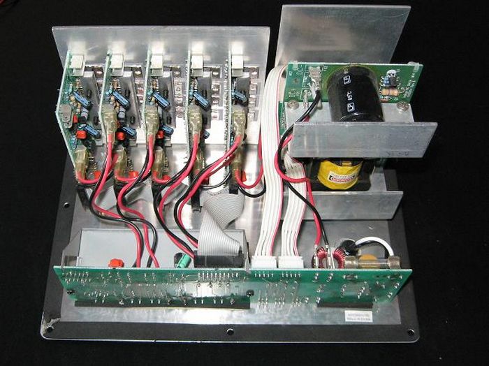
Photo Gallery
Copyright Dale Thompson,
December 10, 2007 through
last revision on August 25, 2012